
Quicklane Vehicle Inspection Training and Courtesy Inspection Guide
Master the multi-point inspection process with precision, efficiency, and professional automotive expertise
by Brian Hagopian
Efficiency is the engine of a successful service bay, but thoroughness is the fuel. In the fast-paced world of automotive maintenance, the ability to perform a precise Vehicle Checkup (VCU) is what separates a technician from a true professional. Brian Hagopian’s Quicklane Vehicle Inspection Training and Courtesy Inspection Guide is the definitive roadmap for mastering the multi-point inspection. This comprehensive instructional manual breaks down the complexities of vehicle diagnostics into a streamlined, step-by-step procedure. From the initial interior walkthrough to underhood fluid analysis, and from undercar structural integrity to critical brake and tire safety checks, no detail is left to chance. Whether you are a novice technician looking to build a rock-solid foundation or a seasoned veteran aiming to shave minutes off your service time without sacrificing quality, this guide provides the clarity and structure you need. Learn how to identify potential issues before they become hazards, build trust with your customers through transparent reporting, and elevate the standard of care for every vehicle that enters your lane. Don't just inspect—examine with the authority of an expert.
- Instructional Guide
- Automotive Repair
The Service Excellence Workflow: From Data Collection to Final Recommendation
The automotive repair industry has changed completely over the last few decades, with modern vehicles now containing over 100 million lines of software code compared to simple mechanical systems of the past. Performing a vehicle checkup inspection is no longer just about popping the hood, wiping a dipstick, and kicking the tires. Modern automobiles are complex systems controlled by dozens of interconnected microprocessors, advanced safety equipment, and precision mechanical components. When a vehicle enters the service bay, the customer relies on our technical expertise to tell them exactly what is happening under the sheet metal. Performing a professional inspection requires a systematic flow across the entire vehicle footprint. If a technician does not follow a structured routine, items get missed. Missed items lead to safety risks, unaddressed maintenance problems, customer complaints, and lost revenue for the shop. Establishing a repeatable, efficient rhythm is the foundation of professional service excellence. By moving logically from the vehicle interior to the engine bay, raising the vehicle for an undercar evaluation, and taking precise measurements of the stopping and steering components, you ensure every system gets evaluated accurately without wasting time or physical energy.
Every phase of the inspection process must be treated with equal importance to maintain strict safety standards and protect the shop from liability. A technician who skips the cabin air filter check during the underhood phase or fails to measure tire tread depth across three distinct points is not completing a true Vehicle Checkup Inspection (VCU). The service workflow is designed to move you fluidly around and under the vehicle. This step-by-step approach eliminates dead time, cuts down on unnecessary movement around the bay, and creates a consistent experience for every customer who hands over their keys. A properly executed VCU serves as a complete health assessment of the vehicle. It provides the service advisor with the precise data needed to communicate repairs clearly to the vehicle owner. When you build a habit of sticking to the exact same inspection path on every car, your speed increases, your accuracy improves, and the quality of your work reaches professional shop standards.
Required Tools, Equipment, and Bay Preparation
Before pulling a vehicle into the service bay, you must ensure you have the proper tools organized and ready to use. Attempting to conduct a thorough multi-point inspection while hunting for missing tools wastes time and disrupts your inspection rhythm. The modern automotive bay requires both traditional mechanical gauges and electronic diagnostic tools to properly evaluate vehicle health. Having these tools calibrated and functioning at the start of every shift is a baseline requirement for modern automotive service.
The following physical and electronic tools are required to perform a standard VCU:
- Digital Battery Tester: Must be capable of printing or digitally exporting test results, showing measured cold cranking amps (CCA), state of charge, and overall battery health.
- Tread Depth Gauge: Must feature increments measured in 32nds of an inch. A digital depth gauge is preferred for fast, accurate reads, but a standard manual mechanical slide gauge is also acceptable.
- Brake Lining Thickness Gauge: A set of color-coded feeler gauges calibrated in both millimeters and fractions of an inch to accurately measure friction material remaining on inner and outer brake pads.
- High-Lumen LED Inspection Light: A rechargeable light with a wide beam pattern and a focused spot beam, generating at least 500 lumens to illuminate dark areas under the hood and chassis.
- Tire Pressure Gauge: A calibrated pressure gauge capable of measuring pounds per square inch (PSI) accurately up to 100 PSI to handle passenger and light truck applications.
- Tablet or Digital VCU Interface: A shop-grade mobile device or terminal running the shop's software platform for logging measurements, taking photos, and documenting component conditions in real time.
- OBD-II Code Reader or Scan Tool: An electronic diagnostic unit to scan for pending, active, or stored Diagnostic Trouble Codes (DTCs) and monitor vehicle system readiness monitors.
In addition to diagnostic equipment, protecting the customer's property is critical before touching any interior controls. Professionalism requires taking immediate steps to prevent transfer of grease, oil, or shop dirt onto customer upholstery and flooring. The initial vehicle setup must include installing protective disposable covers over the driver's seat, placing a paper floor mat in the footwell, and applying a steering wheel wrap. Technicians should always wear clean shop attire and clean work gloves during the interior phase of the inspection. Cleanliness directly affects customer trust. A customer who finds a grease mark on their steering wheel or carpet will doubt the quality of the mechanical work performed under the hood, regardless of how well the service was done.
Calibrating your tools at the start of every shift prevents costly errors. A tread depth gauge that has been dropped can read incorrectly by 2/32ths of an inch, which is the exact threshold between a safe tire and an unsafe tire requiring immediate replacement. Digital battery testers must have clean, uncorroded lead clamps to avoid false resistance readings that cause good batteries to fail or bad batteries to pass. Take two minutes before your first vehicle enters the bay to test your battery clamps, check your gauge zeroes, and ensure your tablet battery is fully charged. This small habit pays off in smooth, uninterrupted workflow throughout the day.
Preliminary Data and Diagnostic Scanning
The inspection begins before the vehicle even leaves the parking lot or intake drive. The first step involves gathering core vehicle identification data and assessing diagnostic status. Accurately matching the physical vehicle to the Repair Order (RO) prevents misdiagnoses, incorrect part orders, and administrative mistakes that delay job completion.
Start by verifying the Vehicle Identification Number (VIN) located on the driver's side dashboard plate visible through the windshield, and cross-reference it with the driver's door jamb safety certification label. Record the exact mileage from the instrument cluster odometer. Do not round the mileage to the nearest thousand; write down the exact number displayed. Accurate mileage logs are necessary for tracking component wear intervals, validating warranty coverage claims, and cross-referencing maintenance schedules recommended by the original equipment manufacturer (OEM).
Turn the ignition key to the "ON" position without starting the engine to execute the instrument cluster bulb check. Ensure all warning lights illuminate, including the Check Engine (MIL), Anti-lock Braking System (ABS), Supplemental Restraint System (SRS), Electronic Power Steering (EPS), and Tire Pressure Monitoring System (TPMS) indicators. If a light fails to illuminate during the bulb check, the bulb or cluster circuit may be damaged or intentionally disabled. Start the engine and observe which warning lights turn off and which remain illuminated on the dashboard.
Connect your OBD-II scan tool or code reader to the vehicle's Data Link Connector (DLC), typically located on the underside of the driver's side dash panel. Run a quick health scan to check for active, pending, or permanent diagnostic trouble codes. Even if the Check Engine light is off, pending codes can reveal developing issues such as intermittent engine misfires, evaporative emission system small leaks, or transmission slip conditions. Document all stored codes on the digital VCU form. Modern fleet management and retail service programs rely on this diagnostic check to catch engine management issues before they cause full vehicle breakdowns.
Step 1: The Interior and Electronics Check
With the engine running and the safety covers in place, begin the systematic inspection of the vehicle's interior controls and passenger cabin electronics. Move through this phase using a circular pattern inside the cockpit to avoid double-checking controls or skipping features. Start at the driver's door panel and work across the instrument panel to the center console, then complete the interior sweep at the passenger side and overhead console.
Test the horn operation by giving it a quick tap. Verify that the turn signal stalk operates smoothly and that the interior direction indicators flash at a normal rate. A rapid flashing signal indicator immediately signals a burned-out exterior bulb on that circuit. Operate the windshield washer fluid pump and check the wiper blades. Inspect the wiper blades for torn rubber edges, splitting along the blade frame, oxidation, or chatter across the glass surface. Spray fluid onto the windshield to evaluate spray nozzle alignment and wiper sweep coverage. A streaking wiper blade is a safety hazard during wet weather and must be documented for replacement.
Move your attention to the Heating, Ventilation, and Air Conditioning (HVAC) system. Turn the blower motor through every fan speed setting, listening for abnormal noises such as ticking from debris in the blower motor cage or squealing from worn bearings. Switch the air delivery modes from defrost to panel to floor, confirming that the mode door actuators function and route air to the correct vents. Set the temperature to maximum heat and verify warm air output, then switch to maximum cooling with the A/C engaged to test the system's ability to pull heat from the cabin. Take note of any musty odors coming from the vents when the fan operates. A sour smell usually indicates mold or fungal growth on the evaporator core or a heavily clogged, damp cabin air filter that needs immediate service.
Check all power window switches from the master driver door panel, raising and lowering each window completely to verify smooth travel without binding, slow operation, or grinding noises. Check the power side mirror adjustments, interior dome lights, hazard warning flasher switch, and power door locks. Finally, press the brake pedal down firmly. Note if the pedal feels spongy, sinks slowly toward the floorboard under steady pressure, or offers a firm response. A spongy pedal indicates air in the hydraulic brake lines or an internal seal failure within the brake master cylinder.
Step 2: Underhood Inspection and Fluid Diagnostics
Pop the hood release lever inside the cabin, step out of the vehicle, and raise the hood, securing it with the prop rod or verifying that the hood lift supports hold the hood up safely. Never work under a hood supported by failing gas struts. Place fender covers over the front fenders to protect the vehicle's paint from belt buckles, zippers, and tool scratches. The underhood phase evaluates the powertrain, electrical system, fluid health, and secondary filters.
Begin by running a complete test on the vehicle's 12-volt battery using your digital battery analyzer. Connect the red positive lead to the positive battery terminal and the black negative lead to the negative battery terminal. Input the battery's rated Cold Cranking Amps (CCA), which is printed on the top or side battery label. Execute the test and examine the printout or tablet readout. Check the measured CCA output, open-circuit voltage, and internal resistance. Visually inspect the battery case for bulging sides, cracked plastic, leaking electrolyte, and corrosion on the terminal posts or hold-down bracket. Clean off minor surface corrosion, but recommend replacing batteries that show structural damage, low CCA test results, or heavy terminal degradation. Print or digitally attach the battery test result strip to the repair order for the customer.
Next, evaluate all underhood fluids for volume level, clarity, and signs of contamination. Pull the engine oil dipstick, wipe it clean on a white shop towel, reinsert it fully, and pull it back out to read the level. Note whether the oil level is at the full line, low, or critically below the minimum mark. Observe the color and clarity of the oil on the towel. Fresh oil is clear and light amber. Dark, opaque black oil indicates the vehicle is due for an oil change. White, milky oil on the dipstick indicates cooling system fluid leaking into the oiling system, which usually means a blown head gasket or cracked engine block. A strong smell of gasoline on the dipstick points to fuel dilution caused by leaking fuel injectors or incomplete combustion.
Inspect the engine cooling system. Examine the coolant recovery tank or radiator overflow bottle level. Never open a hot radiator cap under pressure. Inspect the condition of the engine coolant through the clear expansion tank. Coolant should be bright green, orange, yellow, or pink depending on the OEM chemical spec, and completely free of rust scale, oil film, or debris. Use a coolant refractometer or hydrometer to measure the freeze protection point of the fluid, making sure it protects down to the appropriate temperature for your region. Check all upper and lower radiator hoses, heater hoses, and bypass lines for cracking, bulging, soft spots near clamps, or hard calcified leaks at plastic junction fittings.
Continue checking the remaining underhood fluids using a clear process:
- Brake Fluid: Inspect the master cylinder reservoir level against the min/max lines on the translucent plastic body. Test the fluid's moisture content using a calibrated electronic brake fluid tester or chemical test strip. Brake fluid is hygroscopic and absorbs moisture over time. A moisture content exceeding 3% significantly lowers the fluid's boiling point, creating brake fade during heavy stopping, and requires a complete fluid flush. Check for dark, murky fluid contaminated with suspended rubber particles from degrading internal seals.
- Power Steering Fluid (if applicable): For vehicles equipped with hydraulic power steering, check the dipstick attached to the reservoir cap or inspect the reservoir body level. Inspect fluid color; fresh fluid is usually red or clear light amber. Dark, burnt-smelling fluid indicates thermal breakdown from pump heat and requires replacement. Inspect lines connecting to the pump and rack for weeping or dripping fittings.
- Automatic Transmission Fluid (if equipped with a dipstick): With the vehicle parked on level ground and running at normal operating temperature, pull the transmission dipstick. Verify fluid level and check the color. Healthy automatic transmission fluid is bright red or pink. Dark brown or black fluid accompanied by a sharp burnt smell indicates worn friction clutch plates and severely degraded fluid that can no longer protect internal planetary gear sets.
Examine the engine drive belts and accessory drive system. Use your inspection light to view the ribbed undersides of serpentine belts. Check for longitudinal cracking along the ribs, transverse cracks across ribs, frayed fabric backing, chunking where belt material has torn away, or glaze on the flat side caused by slippage. Press down on the longest span between pulleys to verify automatic belt tensioner operation or proper manual belt tension setting. Spin reachable idler pulleys with the engine off to listen for dry, grinding bearings.
Remove the engine air filter housing cover and take out the air filter element. Hold the filter up toward your inspection light or the sun. If light cannot pass through the filter pleats, or if the pleats are packed with dirt, leaves, insects, or debris, the filter must be recommended for replacement. Inspect the inside of the air filter housing for dirt contamination or oil blow-by coming through the PCV system. Next, locate and remove the cabin air filter, which is typically accessed through the glove box compartment or under the cowl panel. Cabin air filters trap dust, pollen, and debris before air enters the passenger compartment. A heavily clogged cabin air filter chokes off HVAC blower airflow, increases strain on the blower motor, and causes foul smells inside the vehicle. Showing a dirty cabin filter directly to a customer is one of the clearest ways to demonstrate necessary maintenance.
Step 3: Undercar Inspections and Structural Components
Once underhood checks are finished, prepare to raise the vehicle on the lift for undercar evaluation. Set the hoist lifting arms precisely at the manufacturer's designated frame pads or pinch welds. Raising a vehicle on incorrect lift points can crush rocker panels, damage floor pans, or cause the vehicle to shift dangerously while raised. Raise the vehicle approximately knee-high first, then stop and lift up on the front and rear bumpers to perform a quick stability check before raising the vehicle to full working height.
Position your high-lumen LED light and begin a complete visual sweep of the vehicle's undercarriage, working systematically from the front bumper to the rear bumper. Focus first on identifying fluid leaks from the engine, transmission, transfer case, and differentials. Fluid leaks must be accurately diagnosed and described by severity. Differentiating between a light seep and an active drip is essential for proper reporting:
- Class 1 Leak (Seep/Wetness): Fluid is visible on a component surface, gasket, or seal, but has not accumulated enough to form drops or actively fall from the component. This condition should be documented as a "Yellow" recommendation, noting that the component should be monitored at future service intervals.
- Class 2 Leak (Active Leak/Drip): Fluid has accumulated on the component, forming active droplets that drip onto the floor or spray onto surrounding chassis parts while driving. This presents an immediate performance risk, potential environmental hazard, and fluid starvation danger to mechanical components. This must be documented as a "Red" recommendation requiring immediate repair.
Inspect the exhaust system along its entire length. Start at the engine exhaust manifolds, moving rearward past the flexible joint pipe, catalytic converters, resonators, muffler, and tailpipe tips. Look for dark gray or black soot marks along pipe seams and flange gaskets, which signal active exhaust leaks. Exhaust gas leaks entering the passenger cabin create a severe safety hazard from carbon monoxide poisoning. Check the integrity of all metal exhaust hangers and rubber isolator bushings. Rusted, broken, or missing hangers allow the exhaust pipe to bounce, causing metal fatigue, severe vibration, and eventual pipe fracture.
Evaluate front and rear suspension components carefully. Inspect shock absorbers and strut bodies for oil dampness or wet fluid coating the main body shaft, which indicates internal seal failure. A blown shock absorber allows uncontrolled suspension bounce, accelerating tire wear and reducing highway stability. Inspect control arm bushings, trailing arm bushings, and subframe mounts for dry rot, deep rubber splitting, tearing, or off-center alignment where the rubber has completely separated from its metal sleeve. Use a pry bar to apply light leverage against control arm bushings and ball joints, feeling for excess play or looseness. Inspect ball joint dust boots for torn rubber, which allows road grit to destroy the precision ball socket.
Check the steering linkages and drivetrain components. Inspect tie rod end boots and rack-and-pinion inner bellows boots for rips, tears, or fluid pooling inside the rubber accordions. A leaking steering rack boot indicates internal rack seal failure. Grab the front tires at the 9 o'clock and 3 o'clock positions and wiggle the assembly side to side to check for inner and outer tie rod end play. Grab the tires at the 12 o'clock and 6 o'clock positions and rock them in and out to test for wheel hub bearing assembly play and upper/lower ball joint looseness. Any noticeable clunking or mechanical movement during these hands-on stress checks indicates component wear that directly affects vehicle safety and steering control.
Inspect front-wheel-drive (FWD) and all-wheel-drive (AWD) axle shafts and constant-velocity (CV) boots. Flex the rubber CV boots open with your fingers to inspect deep down inside the folds. Cracked or torn CV boots throw protective grease out over the inner wheel well and allow dirt into the precision joint, leading to loud clicking noises on turns and eventual axle failure. For rear-wheel-drive (RWD) vehicles, check the drive shaft universal joints for rust dust around the bearing caps, which signals dry, failing needle bearings. Check the rear differential housing for fluid leaks around the pinion seal and side axle seals.
Step 4: Stopping and Steering Systems
The evaluation of stopping and steering components requires precise measurements rather than visual estimation. Customers rely on accurate brake lining thickness and tire tread depth data to make informed decisions about their vehicle's safety. Never guess brake pad thickness or tire tread life. Use physical measurement tools on every single wheel position during every inspection.
Begin by measuring the remaining friction material on the brake pads or shoes at all four wheel positions. Using a dedicated brake lining thickness gauge or precision micrometer, measure the distance from the metal backing plate to the friction surface of the pad. You must check both the inner pad and the outer pad on every brake caliper. Brake pads frequently wear unevenly due to sticking caliper slide pins, corroded pad abutment slides, or seized caliper pistons. Documenting only the easy-to-see outer pad can result in missing a completely worn-out inner pad that is grinding directly against the rotor face.
Examine the surface condition of the brake rotors. Look for severe rust ridges along the outer diameter lip, deep scoring grooves across the sweeping face, heat spots with blue discoloration, or cracks extending through the rotor surface. If the brake pedal pulsed during your preliminary drive or check, use a dial indicator to measure rotor lateral runout and a brake disc micrometer to measure parallel thickness variation. Record rotor condition alongside pad measurements.
Tire inspection requires measuring tread depth across three distinct locations across the tire's tread face: the outer shoulder, the center tread rib, and the inner shoulder. Place your tire tread depth gauge into the main tread grooves at these three points and record the exact measurement in 32nds of an inch. Measuring across three distinct points is critical for identifying alignment problems, suspension wear, and improper inflation pressures long before the tire fails completely:
- Inner Edge Wear: Indicates excessive negative camber or excessive toe-out, often caused by sagging suspension springs, worn control arm bushings, or bent tie rods.
- Outer Edge Wear: Indicates excessive positive camber or excessive toe-in, often caused by hard curb impacts or improper alignment settings.
- Center Tread Wear: Indicates persistent over-inflation. High air pressure causes the center of the tread to bulge outward, carrying the weight of the vehicle while lifting the outer shoulders off the road surface.
- Dual Shoulder Wear: Indicates persistent under-inflation. Low air pressure causes the center of the tire face to collapse slightly, concentrating vehicle weight on the outer edges of the tire carcass.
- Cupping or Scalloping: Wavy, scooped-out dips along the tread face indicate severe wheel imbalance, worn shock absorbers, or failing struts that allow the tire to bounce down the road.
Inspect tire sidewalls carefully for weather cracking, bulging bubbles caused by impact damage to the internal cord plies, cut rubber, or embedded punctures like nails and screws. Check the DOT tire manufacturing date code printed on the sidewall. The four-digit code represents the week and year the tire was produced (e.g., "1221" means the 12th week of 2021). Tires older than six years require close inspection for rubber degradation, while tires over ten years old should be recommended for replacement regardless of remaining tread depth due to structural rubber breakdown.
Do not forget to inspect and service the spare tire. Lower the spare tire if mounted beneath the truck bed or cargo floor, or open the rear trunk compartment to access it. Measure the spare tire tread depth and adjust its air pressure to the spec listed on the vehicle's door jamb placard. Spare tires are often forgotten until a roadside emergency occurs, and finding a flat or dry-rotted spare leaves the customer stranded. If the vehicle uses an inflation kit instead of a spare tire, check the expiration date stamped on the tire sealant bottle.
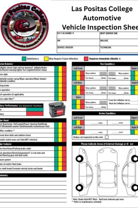
Condition Standards: Green, Yellow, and Red Systems
To communicate inspection results clearly to service advisors and vehicle owners, the automotive service industry uses a standardized three-tier color coding system. Understanding these condition standards ensures consistent, objective reporting across all service bays in a shop. Recommendations must always be backed by accurate physical measurements and technical facts, eliminating subjective opinions or aggressive sales tactics.
The following standards define how components must be categorized on the VCU report:
'Green' Condition: Safe and Fully Operational
The 'Green' status indicates that the component, system, or fluid meets all OEM operating specifications, exhibits normal wear consistent with age and mileage, and requires no immediate service or maintenance. Examples include:
- Brake pad lining thickness measuring 6mm (8/32") or greater with even wear across inner and outer pads.
- Tire tread depth measuring 6/32" or greater with even wear across all three tread zones.
- Fluids that are at correct operating levels, display clean original color, and show no signs of contamination or moisture buildup.
- Battery testing above 80% of rated Cold Cranking Amps with clean terminals and secure physical mounting.
- Underhood belts and hoses showing no cracking, soft spots, fraying, or noise.
'Yellow' Condition: Approaching End of Life / Servicing Suggested Soon
The 'Yellow' status indicates that the component is functional but shows significant wear, minor fluid degradation, or age-related deterioration. Servicing will be required in the near future. Assigning a component 'Yellow' alerts the customer so they can budget for future maintenance before a sudden breakdown or safety risk occurs. Examples include:
- Brake pad lining thickness measuring between 3mm and 5mm (4/32" to 5/32").
- Tire tread depth measuring between 4/32" and 5/32", or showing early signs of uneven edge wear that requires a wheel alignment.
- Brake fluid showing 2% to 3% moisture content, or power steering fluid showing dark color but no burnt odor.
- Class 1 fluid seeps (wetness around a gasket or seal without active dripping).
- Serpentine drive belts displaying light surface cracking (e.g., three or more cracks per inch of belt length) without missing chunks or cord exposure.
'Red' Condition: Safety Hazard / Immediate Repair Required
The 'Red' status signifies an immediate safety hazard, component failure, or condition that puts the vehicle operator at risk or will cause severe secondary damage if not addressed immediately. Assigning a 'Red' status requires immediate documentation and clear communication to the service advisor. Examples include:
- Brake pad lining thickness measuring 2mm (3/32") or less, or friction material wearing down to metal backing plate contact.
- Tire tread depth measuring 3/32" or less (with 2/32" being the legal minimum wear bar limit), or tires with exposed cord plies, sidewall bulges, or severe tread separation.
- Class 2 active fluid leaks (dripping onto the ground or spraying undercarriage parts).
- Battery testing below failing CCA limits, showing internal cell short circuits, or possessing cracked, leaking cases.
- Structural suspension looseness, including severe ball joint play, completely torn CV boots slinging grease, or missing exhaust hangers causing exhaust pipe dragging risks.
Professional Documentation and the Customer Analogy
An inspection is only as good as its documentation. A technician can perform a thorough multi-point inspection, but if the findings are poorly recorded, incomplete, or lack physical proof, the customer will likely decline the recommended services. Clear, transparent documentation builds long-term trust with customers and protects the shop against liability disputes.
When filling out the digital VCU form or physical checklist, follow the standard VCU comment template for every recommended item. Using a standardized comment structure ensures that the service advisor receives complete, professional, and consistent information that can be translated directly into a customer estimate:
Standard VCU Comment Template:
"Observed [Component] at [Measurement/Condition]. Recommend replacement due to [Safety/Performance Risk]."
Apply this template directly to your inspection entries. For example, instead of writing "brakes bad," write: "Observed front inner brake pads at 2mm thickness. Recommend replacement due to severe reduction in stopping power and risk of rotor damage." Instead of writing "leaking shock," write: "Observed rear passenger shock absorber with Class 2 active fluid leakage from main seal. Recommend replacement due to reduced tire contact and uncontrolled vehicle bouncing."
Digital inspection tools allow technicians to attach high-resolution photos and short videos directly to the inspection report. Take advantage of this capability on every "Yellow" and "Red" finding. Capture a clear photograph showing the actual measurement on your digital gauge resting against the tire tread or brake pad. Take clear photos of active oil leaks with your high-lumen light illuminating the fluid drop. When customers see high-definition photos of their own vehicle's worn parts with diagnostic gauges in place, approval rates for needed repairs increase while customer doubts disappear.
Explain mechanical issues clearly to vehicle owners by using simple, relatable comparisons. Non-technical customers often struggle to understand industry jargon like "friction material," "camber wear," or "hygroscopic breakdown." Equating mechanical components to everyday objects helps customers quickly understand why a repair is necessary. Use clear customer-facing analogies during reporting:
Customer-Facing Analogy for Brakes:
"Your brake pads are like the soles of your shoes; once they wear down to the base, you lose traction and safety, damaging everything underneath."
Customer-Facing Analogy for Engine Air Filters:
"Your engine air filter is like a mask for your car; if it gets packed with dirt, the engine has to work twice as hard to breathe, burning far more fuel."
Customer-Facing Analogy for Brake Fluid Moisture:
"Brake fluid absorbing water is like a sponge sitting in a bucket; once it gets saturated, water pockets form inside the brake lines, boiling under heavy stopping and leaving you with a soft pedal."
Best Practices and Common Mistakes to Avoid
Developing speed and accuracy in the service bay takes practice and discipline. Master technicians build high efficiency not by rushing through steps, but by removing useless movements and sticking to a consistent inspection sequence. Every step in the workflow must follow the same order every time a car enters your bay. Consistency prevents missed items, lowers shop stress, and protects shop productivity.
Be aware of common mistakes that lead to misdiagnoses, lost sales, or customer complaints:
- Guessing Brake Pad Thickness: Never estimate brake pad life visually through wheel spokes. Always use a calibrated brake lining thickness gauge. An inner pad can be completely worn out while the outer pad shows plenty of remaining life.
- Skipping Spare Tire Inspection: Failing to check the spare tire's pressure and condition leaves the customer vulnerable to being stranded on the road with a flat spare tire.
- Ignoring the Cabin Air Filter: Skipping the cabin air filter during the underhood phase wastes a primary customer comfort and maintenance opportunity. Cabin filters are usually dirty and easy to present visually to vehicle owners.
- Failing to Document the 'Why': Marking a component "Red" without writing down the specific reason or measurement creates confusion for the service advisor and leads to declined repairs. Always provide the measurement and explain the safety risk.
- Leaving Greasy Fingerprints: Touching steering wheels, door handles, gear shifters, or white exterior paint with dirty gloves destroys customer trust instantly, regardless of how well the mechanical repairs were executed.
Implement a continuous improvement checklist for every vehicle inspection. Before lowering the hoist and clearing the vehicle for delivery to the customer, run through a rapid mental check to make sure no detail was missed:
- Confirm all instrument panel dashboard warning lights are off and diagnostic tools are disconnected.
- Verify tire inflation pressures on all four mounted tires and the spare tire match the vehicle's door jamb placard specs.
- Ensure the printed or digital battery test strip is physically attached to the Repair Order.
- Check that all underhood caps—including engine oil cap, dipstick, brake fluid reservoir, coolant cap, and windshield washer reservoir—are fully tightened.
- Perform a final exterior walk-around using a clean microfiber cloth to remove grease or smudge marks from door handles, hood edges, and the steering wheel before returning the keys.
Executing a standard Vehicle Checkup Inspection with high consistency, clear data logging, and honest reporting is the foundation of professional automotive service. When you respect the inspection workflow, use your tools properly, and communicate findings clearly through precise documentation, you raise the quality of your work, protect customer safety, and establish yourself as an expert technician in the modern automotive service field.