
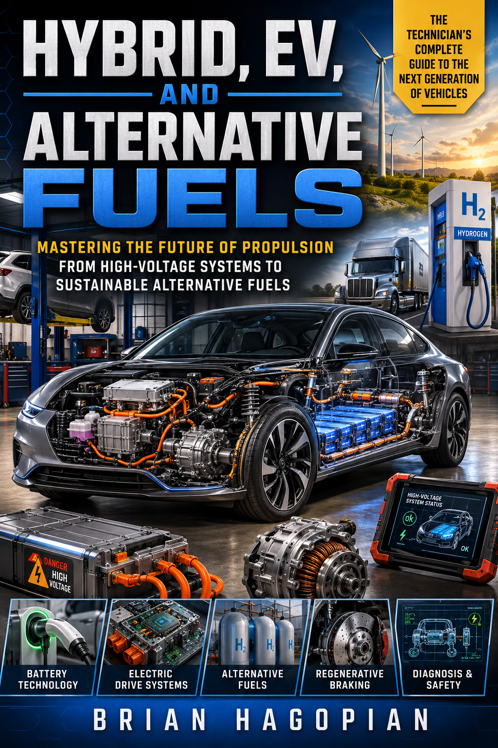
Hybrid, EV, and Alternative Fuels
Mastering the future of propulsion from high-voltage systems to sustainable alternative fuels
by Brian Hagopian
The automotive landscape is shifting at a lightning pace, and the traditional internal combustion engine is no longer the sole king of the road. Hybrid, EV, and Alternative Fuels is the definitive technical guide designed to prepare the next generation of technicians for this high-voltage revolution. This comprehensive textbook goes beyond the basics, offering a deep dive into the engineering and maintenance of modern propulsion systems. From the chemical intricacies of lithium-ion battery management to the mechanical complexity of electronic continuously variable transmissions (eCVTs), student technicians will gain the hands-on knowledge required to excel in a sophisticated workforce. Lab sheets are included for every chapter for hands-on learning. The perfect textbook for your Hybrid/EV class. Inside, you will find detailed explorations of traction motors, regenerative braking, and the critical safety protocols for high-voltage cabling. The text features dedicated chapters on industry giants—including Tesla, Rivian, Toyota, GM, Mazda, Slate, Hyundai, KIA, and Ford—to ensure readers understand the proprietary technologies they will encounter in the shop. Furthermore, it provides a vital technical framework for alternative fuels like hydrogen, CNG, and propane, as well as the emerging world of heavy-duty EV trucking. Equip yourself with the expertise to diagnose, service, and master the vehicles of tomorrow. The future is electric, and it starts here.
- Educational & Academic
- Automotive
The Evolution of Propulsion: Classifying Hybrid and Electric Vehicles
The automotive service industry is undergoing the most significant technological transformation since the transition from horse-drawn carriages to the assembly line. For over a century, the internal combustion engine was the undisputed king of passenger transportation. Automotive technicians spent their careers mastering the nuances of spark ignition, compression ratios, mechanical valve timing, and hydraulic automatic transmissions. Those days are gone. Today, a technician is just as likely to hook up an oscilloscope to diagnose a three-phase alternating current traction motor or use a scan tool to balance the cell voltages of a three-hundred-volt lithium-ion battery pack as they are to perform a compression test on an engine. This shift is not a gradual trend that will happen in the distant future. It is happening right now in repair shops, dealerships, and fleet maintenance facilities across the country. To remain relevant in this modern workforce, a technician must understand how these advanced propulsion systems operate, how they are classified, and how to service them safely.
This rapid evolution is driven by both regulatory mandates and consumer demand for cleaner, more efficient transportation. Automotive manufacturers are pouring billions of dollars into research and development to transition their fleets away from fossil fuels. As these new vehicles enter the market, they bring an entirely new vocabulary and set of mechanical principles. We are no longer dealing with a simple machine that converts gasoline into forward motion. Instead, we are working with complex, integrated propulsion platforms that blend chemical energy, electrical energy, and mechanical kinetic energy in real time. For the service professional, this means that the old ways of diagnosing problems by ear or relying on basic mechanical intuition are no longer sufficient. We must develop a deep, analytical understanding of the engineering principles that govern these systems.
Component Overview: The New Anatomy of Propulsion
To understand how modern hybrid and electric vehicles operate, we must first identify the primary components that make up these advanced drivetrains. The traditional powertrain consisted of an internal combustion engine, a transmission, a driveshaft, and a differential. In an electrified vehicle, this layout is replaced or augmented by three core elements: the internal combustion engine, one or more electric motor-generators, and a high-voltage battery system. The way these components interact defines the vehicle's architecture and determines how it must be diagnosed and repaired.
The internal combustion engine in a hybrid vehicle is not the same as the engine in a conventional car. While it still operates on the four-stroke Otto cycle principle, it is typically redesigned for maximum thermal efficiency rather than peak horsepower. Most modern hybrids utilize an Atkinson-cycle engine. In a standard Otto-cycle engine, the intake, compression, power, and exhaust strokes are of equal volume. The Atkinson cycle alters this relationship by keeping the intake valve open during the first part of the compression stroke. This allows a portion of the air-fuel mixture to flow back into the intake manifold, effectively making the compression stroke shorter than the expansion stroke. The result is a highly efficient engine that extracts more energy from every drop of fuel, though it suffers from a loss of low-end torque. Because an electric motor can provide instant torque from zero RPM, the combination of an Atkinson-cycle engine and an electric motor is a perfect match.
The second key component is the electric motor-generator, often abbreviated as MG in service literature. These machines are incredibly compact and power-dense compared to internal combustion engines. Most modern hybrids and electric vehicles use three-phase alternating current permanent magnet synchronous motors or induction motors. These motors do not use brushes, which eliminates a major point of wear and mechanical friction. The term "motor-generator" is precise because these units are fully reversible. When supplied with three-phase AC electricity from the vehicle inverter, they act as motors, producing mechanical torque to propel the vehicle. When driven mechanically by the engine or by the vehicle's coasting wheels, they act as generators, converting kinetic energy back into electrical energy to charge the battery. Most hybrid transaxles house two of these motor-generators, referred to as MG1 and MG2, which work together to manage power distribution.
The third essential component is the high-voltage battery pack. In a standard vehicle, the twelve-volt lead-acid battery is used primarily to start the engine and power basic accessories. In a hybrid or electric vehicle, the high-voltage battery pack is the main energy storage reservoir for propulsion. These packs operate at potentials far exceeding the safety threshold of human skin, typically ranging from sixty volts direct current to over eight hundred volts in modern high-performance electric vehicles. Early hybrid vehicles, such as the first-generation Toyota Prius and Honda Insight, used Nickel-Metal Hydride battery chemistry. While reliable and durable, these batteries have been largely replaced by Lithium-ion formulations in modern vehicles. Lithium-ion batteries offer much higher energy density, meaning they can store more electricity in a smaller, lighter package. This battery pack is not just a collection of cells; it is a sophisticated system complete with its own electronic controllers, temperature sensors, cooling fans or liquid cooling passages, and safety contactors.
Engineering Principles: Torque Blending and Classification Standards
The primary engineering challenge in any hybrid drivetrain is torque blending. Because we have two completely different power sources, an internal combustion engine and an electric motor, the vehicle's control systems must seamlessly combine their outputs to meet the driver's demand for acceleration while minimizing fuel consumption. To understand how this is achieved, we must look at the physical properties of these two power units. An internal combustion engine produces very little torque at low engine speeds; its torque curve rises as RPM increases, peaks in the mid-to-high range, and then falls off. Conversely, an electric motor produces its maximum torque at zero RPM. As the motor spins faster, its torque output remains flat before gradually tapering off at very high speeds. By combining these two distinct torque curves, a hybrid vehicle can achieve smooth, powerful acceleration across the entire speed range.
To analyze and compare these diverse propulsion systems, the automotive industry relies on standardized frameworks. The most important of these is the SAE J1711 standard, established by the Society of Automotive Engineers. This standard provides the guidelines for measuring the fuel economy, emissions, and utility factors of hybrid and plug-in electric vehicles. It establishes a clear methodology for testing vehicles that use more than one source of onboard energy. Under the SAE J1711 framework, vehicles are evaluated based on their energy consumption patterns, separating them into different operating states depending on whether they are consuming stored electrical energy from the grid or operating in a self-sustaining hybrid mode. This standard is critical for regulatory compliance and ensures that manufacturers report comparable performance metrics to consumers.
To organize the vast array of electrified vehicles on the market, engineers and technicians use the HEV/EV Taxonomy Framework. This framework classifies vehicles based on three primary metrics: Category, Power Flow, and Energy Source. By applying this framework, we can instantly understand the mechanical and electrical layout of any vehicle that enters our service bay. The table below outlines this taxonomy, providing a clear reference for the industry-standard classifications.
| Vehicle Class | Abbreviation | Primary Energy Source | External Charging? | Typical Operating Voltage |
|---|---|---|---|---|
| Hybrid Electric Vehicle | HEV | Liquid Fuel (Gasoline/Diesel) | No | 100V to 300V DC |
| Plug-in Hybrid Electric Vehicle | PHEV | Liquid Fuel & Grid Electricity | Yes | 200V to 400V DC |
| Battery Electric Vehicle | BEV | Grid Electricity Only | Yes | 350V to 800V+ DC |
As we examine this taxonomy, we see that the transition from standard combustion vehicles to pure electric vehicles is a spectrum rather than a simple binary division. Each step along this spectrum represents an increase in electrical storage capacity, operating voltage, and the vehicle's reliance on the electrical grid. Understanding where a specific vehicle falls on this spectrum is the first step in performing any diagnostic or repair procedure.
Operational Logic: Driving Modes and Drivetrain Architectures
The internal software control logic of a hybrid or electric vehicle is incredibly complex. It must constantly monitor throttle position, vehicle speed, state of charge of the high-voltage battery, engine temperature, and cabin climate control demands to determine the most efficient operating mode. These modes transition seamlessly without any input from the driver, though they can be observed through the vehicle's instrument cluster or via live data on a scan tool. Understanding these modes is essential for diagnosing drivability concerns, as a failure in one mode may not present itself in another.
The first operating mode is often referred to as "stealth mode" or pure EV mode. In this state, the internal combustion engine is completely shut off. The high-voltage battery supplies direct current to the inverter, which converts it into three-phase alternating current to power the traction motor. The vehicle moves silently, powered solely by electricity. This mode is typically used during low-speed parking lot maneuvers, light acceleration, and steady-state city driving where engine efficiency would be at its lowest. Because the engine is not running, there are zero tailpipe emissions during this phase of operation.
When the driver demands rapid acceleration, or when the vehicle climbs a steep hill, the control system transitions to "power assist mode." In this state, the mechanical demand exceeds what the electric motor can safely deliver on its own, or doing so would deplete the battery too quickly. The system starts the internal combustion engine using one of the motor-generators. Once running, the mechanical torque from the engine is combined with the electrical torque from the traction motor. The two power sources work in tandem, providing maximum acceleration. This torque-blending capability allows manufacturers to use smaller, lighter, and more fuel-efficient engines without sacrificing vehicle performance.
When the driver lifts their foot off the accelerator pedal or applies the brakes, the vehicle enters "regenerative braking mode." In a traditional vehicle, deceleration is achieved by pressing brake pads against metal rotors, converting the vehicle's kinetic energy into wasted thermal energy. In an electrified vehicle, the control system reverses the flow of power. The traction motor is configured to act as a generator, driven by the turning wheels of the coasting vehicle. The mechanical drag of turning the generator slows the vehicle down, while the resulting three-phase alternating current is sent back to the inverter, converted to direct current, and stored in the high-voltage battery. This process recovers energy that would otherwise be lost to heat, significantly increasing the overall efficiency of the vehicle and reducing wear on the mechanical friction brakes.
To understand how these modes are executed mechanically, we must compare the three primary hybrid drivetrain architectures: Series, Parallel, and Series-Parallel (Power-Split) systems. Each architecture has a distinct mechanical and electrical layout, which dictates how torque is transferred to the drive wheels.
In a Series Hybrid architecture, there is no mechanical connection between the internal combustion engine and the drive wheels. The engine's sole purpose is to spin a generator, which produces electricity. This electricity is sent either directly to the traction motor or to the high-voltage battery for storage. The traction motor is the only component that actually turns the wheels. This layout is highly efficient for stop-and-go city driving because the engine can run at its single most efficient speed and load point regardless of vehicle speed. However, it is less efficient at sustained highway speeds due to the multiple energy conversion steps: mechanical to electrical, and then back to mechanical. An example of this philosophy, though with its own unique engineering twists, is the Chevrolet Volt when its battery is depleted.
A Parallel Hybrid architecture takes the opposite approach. In this system, both the internal combustion engine and the electric motor are mechanically connected to the transmission. They can both drive the wheels directly, either individually or together. Typically, the electric motor is sandwiched between the engine and the transmission, often replacing the traditional torque converter. This design is highly efficient for highway cruising because the engine can drive the wheels directly with minimal mechanical loss. However, it is less versatile than other designs because the motor and engine are locked to the same rotational speed, limiting the system's ability to optimize engine efficiency under all driving conditions. Early Honda Integrated Motor Assist systems are classic examples of parallel hybrids.
The industry standard for maximum efficiency and versatility is the Series-Parallel, or Power-Split, hybrid system. This architecture, pioneered by the Toyota Hybrid System and its Electronic Continuously Variable Transmission, combines the best attributes of both series and parallel designs. A power-split system uses a planetary gearset to mechanically link the internal combustion engine, a generator (MG1), and a traction motor (MG2). The engine's power output is split by the planetary gearset: a portion of the torque is sent mechanically to the drive wheels, while the remaining portion is sent to MG1 to generate electricity. This generated electricity can be routed to power MG2, creating a continuous electrical power path, or sent to charge the high-voltage battery. Because the system can continuously vary the ratio between the mechanical and electrical power paths, it functions as a stepless transmission without the use of belts, pulleys, or traditional shifting clutches. It can operate as a pure electric vehicle, a series hybrid, or a parallel hybrid depending on the driving conditions, offering unmatched real-world efficiency.
Diagnostic Parameters: Identifying and Communicating with Electrified Vehicles
Before a technician ever raises a vehicle on a lift or connects diagnostic equipment, they must accurately identify the vehicle's architecture. Treating an advanced plug-in hybrid or battery electric vehicle as if it were a conventional car can lead to misdiagnosis, unnecessary parts replacement, or serious safety hazards. Fortunately, there are several standardized visual and electronic methods for identifying these vehicles.
The first and most reliable method of identification is the Vehicle Identification Number, or VIN. The VIN is a seventeen-character code that contains specific information about the vehicle's country of origin, manufacturer, division, and vehicle attributes. The eighth character of the VIN typically denotes the engine type, which includes specific codes for hybrid, plug-in, and electric drivetrains. When utilizing an electronic service information database, entering the complete VIN will instantly configure the software to display the correct wiring diagrams, component locations, and diagnostic procedures for that specific propulsion system. Additionally, the federal emission control information label located under the hood will clearly state if the vehicle complies with hybrid or clean-fuel standards.
Beyond the VIN, there are several distinct visual cues that instantly identify an electrified vehicle. Under the hood, the most obvious indicator is the presence of high-voltage orange cabling. By international automotive industry standards, any wiring harness or cable that carries high-voltage electricity, typically defined as exceeding sixty volts direct current or thirty volts alternating current, must be wrapped in bright orange conduit or insulation. If you open the hood or look under the chassis and see orange cabling, you are dealing with a high-voltage system. Furthermore, these vehicles feature specific exterior badging, such as "Hybrid," "PHEV," "EV," or manufacturer-specific terms like "E-Tech" or "BlueDrive." Many plug-in vehicles will also feature a secondary fuel door or charge port door located on the front fender or rear quarter panel, housing an SAE J1772 or CCS charge receptacle.
Once the vehicle is inside the service bay and identified, the diagnostic process begins with establishing communication with the vehicle's onboard computers. In a modern electrified vehicle, this is not a single engine control module. Instead, these vehicles rely on a highly complex network of interconnected modules communicating over high-speed Controller Area Network buses and other automotive communication protocols. A typical hybrid system features several specialized control modules, including:
- Hybrid Powertrain Control Module (HPCM): The master controller that orchestrates the overall operation of the system, managing torque requests and operating modes.
- Battery Energy Control Module (BECM): Monitored continuously, this module tracks cell voltages, battery temperature, state of charge, and controls the high-voltage contactors.
- Inverter/Converter Control Module: Controls the high-speed switching of the insulated-gate bipolar transistors to convert DC battery power to three-phase AC power for the motors.
- Transmission Control Module (TCM): Coordinates the mechanical shifting and gear engagement in vehicles with conventional transmissions or manages the eCVT power flow.
When performing initial diagnostics, the technician must connect a compatible diagnostic scan tool to the OBD-II port and perform a complete system health check. This involves querying every module on the data bus for diagnostic trouble codes. A failure in the high-voltage battery system will often set a code in the BECM, which then communicates a fault to the HPCM, resulting in a secondary code and a illuminated warning light on the instrument cluster. Understanding this inter-module communication is critical. If a technician focuses solely on the engine control module, they may miss the root cause of the problem, which is actually stored in the battery control module. Always perform a complete network scan to see the big picture before attempting to isolate a fault.
Service and Safety: High-Voltage Protocols and Personal Protective Equipment
Working on hybrid and electric vehicles is inherently safe if you follow established safety protocols, but it can be lethal if you do not. High-voltage direct current is incredibly unforgiving. Unlike alternating current, which tends to cause muscle spasms that can throw a victim away from the source, direct current causes continuous muscle contraction. If you grab a live high-voltage DC component, your muscles will lock, preventing you from letting go. This current can travel through your heart, causing ventricular fibrillation and cardiac arrest. It can also cause severe internal and external electrical burns. Because of these extreme hazards, safety must be the absolute priority for every service procedure.
The first rule of high-voltage safety is to respect the orange cables. Never touch, pull, cut, or probe any orange cable unless the high-voltage system has been verified as completely depowered. These cables carry the energy needed to propel a two-ton vehicle; they contain more than enough energy to cause fatal injuries. Before performing any service that brings you near high-voltage components, you must perform a high-voltage disable procedure, often referred to as shutting down the system or removing the service disconnect.
Every hybrid and electric vehicle is equipped with a physical high-voltage service disconnect. This is typically a bright orange plug, switch, or lever located on or near the high-voltage battery pack. In some vehicles, it is accessed through a small door in the trunk floor, under the rear seat, or under a panel in the passenger footwell. Removing this disconnect physically breaks the high-voltage circuit, splitting the battery pack into smaller, lower-voltage sections that are below the hazardous threshold. However, simply pulling the plug is not enough to guarantee safety. The system may still hold a high-voltage charge in the inverter's large internal capacitors. These capacitors act as electrical reservoirs, storing energy to smooth out voltage spikes during operation. After removing the service disconnect, you must wait a specified period, typically five to ten minutes, to allow the internal discharge resistors to drain this residual energy before proceeding with any diagnostic or service work.
When working around high-voltage systems, technicians must wear appropriate Personal Protective Equipment. The most important piece of PPE is a pair of high-voltage insulating gloves. These are not standard work gloves; they are specialized rubber gloves designed and tested to withstand high voltages. For automotive applications, Class 0 gloves are the industry standard. These gloves are rated for working voltages up to one thousand volts alternating current and fifteen hundred volts direct current. They must be worn whenever you are disabling the system, verifying the absence of voltage, or working near exposed high-voltage terminals.
Rubber insulating gloves are thin and can be easily punctured by sharp wire strands, bracket edges, or tools. A pinhole leak in a glove can allow electricity to arc directly through to your skin. Therefore, Class 0 rubber gloves must always be worn with a pair of heavy leather outer protectors. The leather protectors shield the delicate rubber gloves from mechanical damage. Before every use, the technician must perform a visual inspection and an air test on the rubber gloves. This involves rolling the glove up from the cuff to trap air inside, then squeezing the inflated glove while holding it close to your ear to listen for any escaping air. If you detect even the slightest leak, the glove must be discarded immediately. Additionally, these gloves must undergo regular professional testing and certification, typically every six months, to ensure their insulating properties have not degraded over time.
Another fundamental safety practice is the "one hand rule." When working on or near high-voltage systems, keep one hand in your pocket or behind your back whenever possible. Electricity requires a complete circuit to flow. If you touch a high-voltage component with your right hand and a grounded metal frame member with your left hand, the path of least resistance for the electrical current is directly across your chest, passing through your heart. By using only one hand to perform measurements or service steps, you prevent the current from establishing a path through your vital organs. This simple habit has saved countless lives in the electrical and automotive industries.
Step-by-Step High-Voltage Safety Verification
To ensure maximum safety in the workshop, every technician must master the process of disabling and verifying that a high-voltage system is safe to work on. This is not a task where you can skip steps or rely on assumptions. It must be executed with methodical precision every single time. Below is the step-by-step procedure that must be followed before performing any service on high-voltage components.
- Establish a Safe Work Zone: Position the vehicle in a designated service bay. Place high-voltage warning signs around the vehicle perimeter to alert other shop personnel that high-voltage work is in progress. Remove all jewelry, watches, rings, and belt buckles, as metal objects can conduct electricity and cause short circuits.
- Power Down the Vehicle: Turn the ignition switch to the OFF position. Remove the key fob from the vehicle and place it in a secure location outside of the vehicle's wireless communication range. This prevents the vehicle from accidentally entering the "Ready" mode while you are working on it.
- Disconnect the Twelve-Volt Battery: Locate the auxiliary twelve-volt battery, which is often positioned in the trunk or under the rear seat in hybrid vehicles. Disconnect the negative ground cable from the battery terminal. This isolates the low-voltage control circuits, preventing the vehicle's onboard computers from commanding the high-voltage system contactors to close.
- Don Your Personal Protective Equipment: Inspect your Class 0 rubber insulating gloves and perform the roll-up air test. Slip the rubber gloves on, followed by the leather outer protectors. Ensure your safety glasses are on and secure.
- Remove the Service Disconnect: Locate the high-voltage service disconnect plug. Following the manufacturer's specific instructions, unlock the safety latch, swing the lever or pull the handle, and remove the plug entirely. Store the disconnect plug in a secure location, such as your toolbox or a locked box, to prevent anyone else from reinstalling it while you are working.
- Wait for Capacitor Discharge: Set a timer for the manufacturer-specified discharge time, typically five to ten minutes. This allows the high-voltage capacitors inside the inverter assembly to discharge their stored energy through the internal bleed resistors. Do not touch any components during this waiting period.
- Verify Zero Voltage: Using a high-quality Digital Multimeter rated CAT III 1000V or CAT IV 600V, verify that your meter is functioning correctly by measuring a known voltage source, such as the twelve-volt battery. Next, remove the high-voltage service cover on the inverter or junction block. Probe the high-voltage test points specified in the service manual. Verify that the voltage between the positive and negative terminals is zero, and that the voltage between each terminal and the vehicle chassis ground is also zero. Finally, re-test your meter on the twelve-volt battery to confirm it is still functioning correctly. Only after this verification is complete can you consider the system safe to service.
This verification process is the absolute foundation of high-voltage service safety. By measuring the voltage and confirming it is zero, you eliminate any guesswork. You are not relying on a light on the dashboard or a software status screen; you are using a calibrated physical tool to prove that the work area is safe. If you ever measure voltage during this process, stop immediately, reinstall the service disconnect if possible, and seek assistance from a senior diagnostic technician or shop supervisor.
The Evolution of Propulsion: A Comparative Analysis
To fully appreciate why these advanced architectures have become so dominant, we must compare them directly to the traditional internal combustion engine powertrain. For over a century, the mechanical efficiency of the internal combustion engine was limited by the laws of thermodynamics. Even the most advanced modern gasoline engines struggle to exceed forty percent thermal efficiency, meaning that over sixty percent of the energy contained in every gallon of fuel is lost as heat to the atmosphere or through the cooling system. This waste is compounded by the mechanical losses in the transmission and drivetrain.
When we look at a battery electric vehicle, the efficiency picture is completely different. Electric traction motors are incredibly efficient, often exceeding ninety percent. This means that nearly all the electrical energy stored in the battery is converted directly into forward motion. There are no idling losses, as the motor simply stops spinning when the vehicle is stationary. There are no multi-speed transmissions wasting energy through hydraulic pumps or wet clutches, as most electric vehicles use a simple single-speed reduction gear. When you combine this high motor efficiency with the energy recovered during regenerative braking, the overall efficiency of a BEV is unmatched by any combustion engine. The biggest remaining problem is cost and infrastructure. Until the industry can produce high-voltage battery packs at a lower cost and build a widespread, reliable fast-charging network, hybrid vehicles will continue to serve as the critical bridge for many consumers.
This brings us to the hybrid electric vehicle, which represents the perfect compromise for our current infrastructure. By pairing a highly efficient Atkinson-cycle engine with one or more electric motors, an HEV can operate in its sweet spot of efficiency almost continuously. The electric motor handles the inefficient, high-load scenarios like starting from a complete stop and low-speed driving. The engine can then focus on steady-state cruising, where its efficiency is highest, while simultaneously generating electricity to replenish the battery. This symbiotic relationship allows modern hybrids to achieve fuel economy figures that were unimaginable a few decades ago, all without requiring the driver to plug the vehicle into an electrical outlet.
Plug-in hybrid electric vehicles take this concept a step further by bridging the gap between HEVs and BEVs. A PHEV features a larger high-voltage battery pack and an onboard charger, allowing it to be plugged into the grid. This gives the vehicle a significant all-electric driving range, typically between twenty and fifty miles. For the average commuter, this means they can drive to work, run errands, and return home entirely on cheap, clean electricity, never starting the internal combustion engine. However, if they need to take a long-distance road trip, the gasoline engine is always there, ready to take over and provide unlimited range using the existing refueling infrastructure. This dual-nature design makes PHEVs incredibly popular, but it also makes them some of the most complex vehicles on the road to diagnose and maintain.
The Impact of Advanced Technology on the Automotive Service Industry
The rapid adoption of hybrid and electric vehicles is fundamentally changing the business model of automotive repair. In the past, shops relied heavily on routine maintenance services like oil changes, spark plug replacements, transmission flushes, and brake jobs to keep their bays full and profitable. Electric vehicles require none of these traditional services. They do not have engine oil, spark plugs, timing belts, oxygen sensors, catalytic converters, or multi-speed transmissions. Even their mechanical brake pads and rotors last significantly longer because regenerative braking handles the majority of the stopping force.
This shift has led some to predict the demise of the independent repair shop, but that view is short-sighted. While the nature of the work is changing, the demand for highly skilled technicians is higher than ever. Electrified vehicles still have steering, suspension, steering joints, wheels, tires, wheel bearings, and complex heating, ventilation, and air conditioning systems. In fact, the air conditioning system is more critical than ever, as it is often used to cool the high-voltage battery pack during fast charging or heavy load conditions. A failure in the cabin AC system can cause the vehicle to disable the high-voltage system entirely to protect the battery from overheating.
Furthermore, these advanced vehicles introduce a host of new service opportunities. High-voltage battery packs will eventually degrade over time, requiring cell balancing, module replacement, or complete pack rebuilding. Traction motors can develop bearing wear or winding insulation faults that require specialized diagnostic equipment to isolate. Inverters and converters use high-power electronics that can fail due to thermal stress. Diagnosing these complex electrical and thermal systems requires a completely different skillset than traditional mechanical repair. The shops and technicians who invest in the training, tools, and safety equipment required to service these advanced propulsion systems will thrive in this new landscape, while those who refuse to adapt will find themselves left behind.
Diagnostic Case Study: Identifying a Hybrid System Fault
To illustrate the practical application of these principles, let us walk through a typical diagnostic scenario involving a series-parallel hybrid vehicle. A customer brings in a third-generation hybrid vehicle with the "Ready" light failing to illuminate on the instrument cluster, and a red triangle warning light glowing on the dashboard. The engine does not crank, and the vehicle will not move.
The first step is to perform a visual inspection and identify the vehicle. By looking at the VIN and the exterior badging, the technician confirms this is a series-parallel hybrid using an electronic continuously variable transmission. The technician notes the presence of high-voltage orange cabling under the hood, confirming the vehicle operates on a high-voltage system. Next, the technician connects a scan tool to the OBD-II port and performs a complete system scan.
The scan tool reveals multiple diagnostic trouble codes stored across different modules. The Engine Control Module shows a code for "Lost Communication with Hybrid Control Module." The Battery Energy Control Module shows a code for "High-Voltage Isolation Fault." The Hybrid Powertrain Control Module shows a code for "Hybrid System Disengaged - Hard Fault." This is a classic example of inter-module communication during a system fault. The isolation fault detected by the battery controller has caused the system to open the high-voltage contactors for safety, which in turn prevents the engine from starting or the vehicle from entering the "Ready" state.
To diagnose the isolation fault, the technician must follow the high-voltage disable and safety verification procedure described earlier. They park the vehicle in a designated bay, set up warning signs, put on their Class 0 gloves, pull the service disconnect, and wait for the capacitors to discharge. After verifying zero voltage at the inverter test points with their CAT III multimeter, the technician can safely begin testing. An isolation fault means that high-voltage electricity is leaking to the low-voltage chassis ground, which is a major safety hazard. Using a specialized megohmmeter (also known as an insulation tester), the technician tests the insulation resistance of the high-voltage cables, the traction motor windings, and the air conditioning compressor. The test reveals a breakdown in the insulation of the electric air conditioning compressor motor. The compressor is replaced, the system is reassembled, the service disconnect is reinstalled, the twelve-volt battery is reconnected, and the codes are cleared. The "Ready" light illuminates, and the vehicle is verified as operating perfectly. This case study demonstrates how a systematic approach, combining safety protocols with advanced diagnostics, is essential for servicing these modern propulsion systems.
Best Practices and Common Technical Mistakes
As technicians transition to working on electrified vehicles, there are several common pitfalls that can lead to misdiagnosis, damaged components, or personal injury. By understanding these common mistakes and adopting industry best practices, you can ensure your work is both safe and efficient.
One of the most common mistakes is treating a plug-in hybrid electric vehicle as if it were a standard hybrid during diagnostic routines. A standard hybrid relies entirely on the internal combustion engine to charge the battery. If the engine is running poorly, it will directly affect the battery's state of charge and the overall performance of the hybrid system. A plug-in hybrid, however, can be charged from the grid. If a customer complains of poor fuel economy or lack of electric-only range in a PHEV, the technician must verify the operation of the onboard charger, the charge port receptacle, and the customer's home charging habits. Simply checking the engine and the hybrid transaxle is not enough. You must analyze the entire charging ecosystem, including the communication protocol between the vehicle and the Electric Vehicle Service Equipment (the charging station).
Another frequent error is failing to check the service disconnect before probing electrical circuits. Some technicians assume that if the ignition is off, the system is safe. However, a stuck-closed high-voltage contactor can keep the entire high-voltage bus energized even with the key removed. This is why physical verification with a multimeter is non-negotiable. Never assume a circuit is dead just because a control module says it is. Always measure the voltage yourself, wearing your Class 0 gloves, to prove the system is safe before touching any metal terminals.
Additionally, technicians often overlook the importance of the twelve-volt auxiliary battery in hybrid and electric vehicles. Because the high-voltage battery does the heavy lifting of starting the engine and propelling the vehicle, the twelve-volt battery is often small and easily discharged. However, this battery is responsible for powering all the control modules, closing the high-voltage contactors, and initiating the startup sequence. A weak or failing twelve-volt battery can cause a massive array of communication codes, random warning lights, and a "no-start" condition that can easily be misdiagnosed as a major high-voltage battery failure. Always test the twelve-volt battery first whenever you encounter weird communication issues or system startup failures.
The Future of the Automotive Workforce
The demand for skilled automotive technicians who understand advanced propulsion systems is at an all-time high, and it will only continue to grow. Employers across the country are struggling to find qualified technicians who can safely and effectively service these vehicles. This shortage represents a massive opportunity for students entering the field today. By mastering these technologies, you can position yourself for a highly paid, secure career in a rapidly evolving industry.
This training is not just about learning how to turn a wrench; it is about developing an analytical, problem-solving mindset. The modern automotive technician is a blend of a mechanical engineer, a software programmer, and an electrical specialist. We must embrace this identity and commit to continuous professional development. Technology changes constantly, and if we do not keep up, our skills will quickly become obsolete. The certifications you earn today, such as the ASE L3 Light Duty Hybrid/Electric Vehicle specialist certification, are highly valued by employers and demonstrate that you are prepared to work on the cutting edge of transportation technology.
This textbook and the associated college course are designed to provide you with the solid foundation you need to launch your career in this exciting field. In the chapters that follow, we will dive deeper into the physics of high-voltage systems, the chemistry of energy storage, the mechanics of traction motors and eCVTs, and the specific proprietary technologies of industry leaders like Tesla, Toyota, and Ford. We will also cover the growing field of heavy-duty EV trucks and alternative fuels like hydrogen and compressed natural gas. By the end of this course, you will have the knowledge and confidence to approach any electrified vehicle with safety and diagnostic precision, prepared to lead the automotive workforce into the twenty-first century.
Chapter Implementation Checklist
To ensure you have mastered the core electrical and safety concepts covered in this chapter and are fully prepared to apply them in a lab or workshop setting, use the following practical checklist before beginning any hands-on high-voltage diagnostic work:
Verify Tool Ratings: Ensure your digital multimeter is physically marked with a CAT III 1000V or CAT IV 600V safety rating and that the leads have no visible cracks or exposed wire.
Perform Glove Air Test: Conduct the roll-up air test on your Class 0 rubber insulating gloves, listening and feeling for leaks to ensure they are 100% airtight.
Check Glove Expiration: Check the physical stamp on your rubber gloves to verify they have undergone professional electrical testing and certification within the last six months.
Locate Service Information: Access the OEM service information database to pull the specific high-voltage disable procedure, component locations, and specified torque values.
Identify Safety Equipment: Locate the shop's high-voltage safety hook and ensure it is easily accessible.
Establish Workspace Boundary: Place high-voltage safety cones and warning signs around your designated service bay to block off unauthorized personnel.
Summary of Key Takeaways
Voltage Mitigates Heat and Weight: Utilizing high voltage (e.g., 400V to 800V+) allows automotive engineers to decrease current levels. This reduction minimizes exponential heat generation ($I^2R$ loss) and allows for lighter, thinner copper cabling.
The 12V Auxiliary System is the Gatekeeper: The high-voltage system cannot deploy its energy unless its electromagnetic contactors are closed, an action that strictly requires a healthy, fully charged twelve-volt auxiliary battery.
Standard Multimeters are Inadequate for Insulation Testing: Standard digital multimeters only output 3V to 9V, failing to expose microscopic insulation cracks that easily arc under true operating potentials. Specialized insulation testers (megohmmeters) must be used.
Isolation is Paramount for Safety: Unlike 12V systems that use the vehicle chassis as a ground return, the high-voltage bus operates as a completely isolated, two-wire floating circuit to prevent lethal shock hazards.
The "Buddy System" is Essential: High-voltage diagnostics should never be performed alone; a trained coworker must be nearby to assist or cut power using a safety hook if an accident occurs.
Summary of Key Concepts
Ohm's Law ($V = I \times R$): Defines the relationship between voltage, current, and resistance, demonstrating how microscopic resistance can create massive voltage drops in high-current paths.
Watt's Law ($P = V \times I$): Outlines electrical power, highlighting why increasing system voltage is the most efficient way to maximize electric drivetrain power output without overloading components.
Isolation Resistance: The measurement of electrical insulation between the floating high-voltage bus and the vehicle's metal chassis ground. International standards require a minimum of 500 ohms per volt of operating voltage.
Pulse Width Modulation (PWM): A digital control scheme where power inverters rapidly cycle Insulated-Gate Bipolar Transistors (IGBTs) on and off to vary the duty cycle, effectively synthesizing variable AC waveforms from flat DC supplies.
Touch Potential: The potential voltage difference between an energized metal object (such as a faulty inverter housing) and the ground surface or another conductive part, which poses an electrocution hazard if bridged by the human body.
Live-Dead-Live Test: A mandatory three-phase testing protocol where a technician verifies multimeter functionality on a live 12V source, checks the high-voltage circuits for zero energy, and re-verifies the meter on the live source to rule out false-zero readings.
Chapter Summary
The modern automotive service landscape has evolved from simple mechanical linkages to high-voltage architectures, shifting electricity from a minor accessory support network into the vehicle's primary fuel source. Electrified vehicles use a split-voltage design: a low-voltage auxiliary system (12V) that manages control modules and safety contactors, and an isolated, floating high-voltage bus (100V to 800V+) dedicated to propulsion and heavy auxiliary loads like A/C compressors and cabin heaters. The physical bridge between these environments is the solid-state DC-to-DC converter.
To safely manage this power, vehicles utilize advanced power inverters equipped with liquid-cooled Insulated-Gate Bipolar Transistors (IGBTs) to seamlessly convert DC battery energy into three-phase AC for traction motors during acceleration, and back into DC during regenerative braking. Diagnosing these systems requires specialized parameters, such as tracking isolation resistance via onboard monitoring and isolating electrical leaks with megohmmeters rather than traditional digital multimeters. Ultimately, a technician's safety relies on strict adherence to established boundary protocols, the High-Voltage Safety Verification Protocol, and proper use of certified Class 0 personal protective equipment.
Conclusion
The transition toward vehicle electrification represents an permanent paradigm shift for automotive repair, transforming the trade from a historically manual labor occupation into a clean, high-tech, and intellectually demanding profession. For technicians and shop owners to thrive, a fundamental mastery of invisible electrical forces, solid-state power components, and rigid safety testing workflows is no longer optional—it is a core prerequisite for the job. By approaching high-voltage architectures with methodical precision, respecting physical laws like Ohm's and Watt's, and consistently executing safety protocols, modern technicians can confidently navigate, diagnose, and master the sophisticated drivetrains of tomorrow.
Chapter Review Questions Multiple Choice
- According to the SAE J1711 standard, what parameters are measured for hybrid and plug-in electric vehicles? A) Peak mechanical horsepower and low-end torque output B) Fuel economy, emissions, and utility factors C) Lithium-ion cell balancing and thermal degradation limits D) Hydraulic automatic transmission pressures and shift points
- Which hybrid drivetrain architecture features no mechanical connection between the internal combustion engine and the vehicle's drive wheels? A) Parallel Hybrid B) Series Hybrid C) Series-Parallel Hybrid D) Power-Split Hybrid
- By international automotive industry standards, what color insulation or conduit must be used to wrap high-voltage wiring harnesses? A) Bright Blue B) Bright Yellow C) Bright Red D) Bright Orange
- Which electronic control module acts as the master controller that orchestrates overall hybrid system operation and manages torque requests? A) Hybrid Powertrain Control Module (HPCM) B) Battery Energy Control Module (BECM) C) Inverter/Converter Control Module D) Transmission Control Module (TCM)
True / False
- An Atkinson-cycle engine achieves high thermal efficiency by keeping the intake valve open during the first part of the compression stroke. (True / False)
- High-voltage direct current (DC) is safer than alternating current (AC) because it causes muscle spasms that throw a victim away from the electrical source. (True / False)
- Before every use, a technician must perform a visual inspection and a roll-up air test on Class 0 rubber insulating gloves. (True / False)
Short Answer
- Why can a weak or failing 12-volt auxiliary battery easily be misdiagnosed as a major high-voltage battery pack failure?
- Explain the purpose of the "one hand rule" and how it protects a technician working around high-voltage vehicle systems.
- After pulling the physical high-voltage service disconnect plug, why must a technician wait a manufacturer-specified period (typically 5 to 10 minutes) before probing test points?
Answer Key
- B — The SAE J1711 standard establishes the methodology and guidelines for measuring fuel economy, emissions, and utility factors of electrified vehicles.
- B — In a Series Hybrid system, the engine's sole purpose is to spin a generator to produce electricity; there is no mechanical link to the wheels.
- D — International industry standards dictate that any wiring harness carrying high-voltage electricity must be wrapped in bright orange conduit or insulation.
- A — The Hybrid Powertrain Control Module (HPCM) is the master controller responsible for managing torque requests and alternating operating modes.
- True — The Atkinson cycle keeps the intake valve open during the initial phase of compression, returning a portion of the mixture to the intake manifold to reduce pumping losses and boost efficiency.
- False — High-voltage direct current causes continuous muscle contraction, locking a victim to the source, making it incredibly unforgiving and lethal.
- True — Technicians must roll up the glove from the cuff to trap air and check for any pinhole leaks before every use, as small punctures can allow electricity to arc to the skin.
- Answer: The 12-volt auxiliary battery powers all the primary vehicle control modules, logs network communications, and commands the high-voltage system contactors to close. A failure here prevents system startup and triggers a massive array of communication codes, masquerading as a catastrophic traction battery failure.
- Answer: The "one hand rule" requires keeping one hand in a pocket or behind the back while servicing high-voltage circuits. This prevents completing a circuit from one arm, across the chest, and through the vital organs/heart to a chassis ground.
- Answer: High-voltage system inverters house large internal capacitors that store high-voltage electricity to smooth out electrical spikes. Technicians must wait for internal bleed resistors to drain this residual capacitor energy completely before it is safe to touch exposed terminals.
Electrical Fundamentals: Voltage, Amperage, and High-Voltage Physics
The transition from mechanical linkages and simple twelve-volt DC circuits to multi-hundred-volt propulsion systems represents a major leap for the automotive service technician. In traditional internal combustion vehicles, electricity was historically treated as an accessory support system. It spun the starter motor, powered the headlights, and ra…