
Automotive Advanced Electrical and Networks Diagnostic Procedures
Master High-Speed Bus Systems and Oscilloscope Diagnostics to Solve Complex Electrical Failures
by Brian Hagopian
Stop Guessing. Start Diagnosing. In today's vehicles, electrical faults don't announce themselves. They hide inside complex networks, encrypted security systems, and high-speed data communications. Every unnecessary part replacement costs time, money, and credibility. The era of the "parts cannon" is over. In Automotive Advanced Electrical and Network Diagnostic Procedures, veteran instructor and diagnostician Brian Hagopian delivers a practical, in-depth guide to mastering the technology that powers modern vehicles. More than a repair manual, this book is a comprehensive diagnostic framework designed to help technicians understand, analyze, and solve the most challenging electrical and communication faults found in today's automotive systems. From the fundamental physics of electricity to advanced diagnostics involving CAN, LIN, K-Line, and immobilizer networks, you'll learn how modules communicate, why systems fail, and how to pinpoint faults with confidence. Using proven methodologies—including the powerful Rule of Three diagnostic strategy—you will develop the skills needed to interpret oscilloscope waveforms, identify network corruption, isolate faulty control modules, and trace elusive wiring and communication issues that often leave less experienced technicians guessing. Through real-world diagnostic scenarios, you'll learn how to troubleshoot complex systems ranging from hybrid auxiliary coolant pumps and body control networks to sophisticated security systems that govern communication between the IMMO, ECM, and other critical modules. Every chapter bridges the gap between theory and practical application, providing procedures you can immediately apply in the shop. Whether you're an experienced technician looking to sharpen your diagnostic edge, an automotive instructor preparing the next generation of professionals, or a student determined to master advanced electronics, this book provides the knowledge and workflows required to achieve accurate, first-time repairs. The automotive industry is evolving faster than ever. Those who understand vehicle networks and advanced electrical diagnostics will lead the future of automotive service. Master the signals. Decode the networks. Diagnose with certainty.
- Instructional Guide
- Automotive Repair
- Electronics Repair
- Technology Guides
Voltage Mastery and the Physics of Pressure
The modern automobile is no longer a collection of mechanical linkages held together by grease and simple wiring. It is a highly integrated, software-driven mobile network. When a vehicle rolls into a service bay with a complex electrical issue, the technician who relies on twentieth-century habits is immediately at a disadvantage. The old approach of using a test light to poke at wires until something glows is not only obsolete, but it can also easily destroy a thousand-dollar control module. To survive and excel in the modern automotive service industry, you must approach electrical systems by systematically tracking voltage drops across active loads and analyzing digital signal waveforms on an oscilloscope. This transition begins with a complete and uncompromising mastery of voltage, the fundamental physical pressure that drives every electrical event in the vehicle.
There is a common misconception among apprentice technicians, and even some seasoned veterans, that electricity is a mysterious liquid flowing through copper pipes. This fluid model breaks down entirely in a digital context, as it fails to explain high-speed binary state transitions or how nanosecond-level electrical pressure changes dictate network logic without physical physical mass displacement. To truly understand voltage, you must set aside the fluid analogies and look directly at the physics of the system. Voltage is not a physical substance. It does not flow through a wire. It is not a kinetic displacement of mass, but rather a static condition of potential. Voltage is Electromotive Force, commonly abbreviated as EMF. It is the electrical pressure created by a difference in charge between two separate points in a circuit.
The Physics of Pressure and Potential Difference
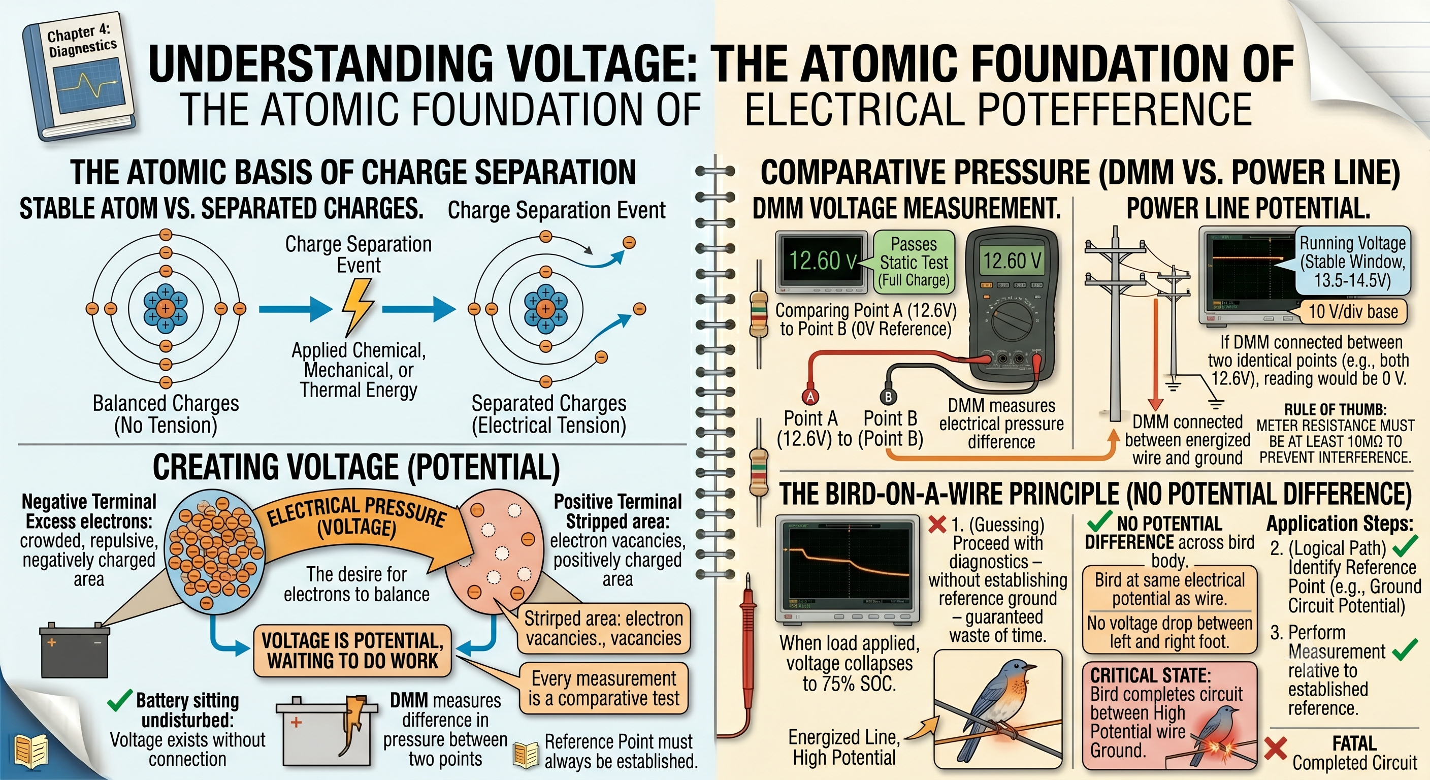
To grasp what voltage actually represents, you must look at the atomic level. All matter is composed of atoms, which contain positively charged protons in their nuclei and negatively charged electrons orbiting around them. In a stable material, these charges are balanced. However, when we apply chemical energy, mechanical energy, or thermal energy, we can cause electrons to separate from their parent atoms. This separation of charge creates an imbalance. One area becomes crowded with excess electrons, giving it a negative charge, while another area is stripped of electrons, leaving behind a positive charge.
This physical separation of charge creates a state of tension. The excess electrons on the negative side are repelled by each other and attracted to the positive side, where there is a vacancy. This state of tension, this electrical pressure born from the desire of electrons to return to a state of balance, is what we measure as voltage. It is critical to recognize that this pressure exists whether those electrons are moving or not. A battery sitting on a workbench has electrical pressure between its positive and negative terminals, even if nothing is connected to it. The voltage is there, waiting, representing the potential to do work. This is why we refer to voltage as potential difference.
When you place the test leads of a digital multimeter across a battery, the meter does not measure the quantity of electricity inside the battery. It measures the difference in electrical pressure between the positive post and the negative post. If both posts had the exact same electrical charge, there would be no difference in pressure, and the meter would display zero volts. This is true even if both posts were packed with trillions of excess electrons. Without a difference in charge between two points, there is no potential difference, no electromotive force, and therefore no voltage. Every voltage measurement you ever perform on a vehicle is a comparative test. You are always measuring how much more pressure exists at point A compared to point B.
This concept of potential difference explains why a bird can sit on a high-voltage power line without being electrocuted. The bird is entirely at the same electrical potential as the wire. There is no difference in pressure between its left foot and its right foot. Because there is no potential difference across the bird's body, no current flows through it. However, if that same bird were to touch the adjacent ground wire while still standing on the energized line, it would instantly complete a circuit between a high-pressure point and a low-pressure point. The potential difference would manifest across its body, current would flow, and the result would be fatal. In automotive diagnostics, you must always identify your reference point. You cannot talk about the voltage at a single pin on a computer module without knowing the electrical potential of the ground circuit to which that module is referenced.
The 12.6V Standard and the Reality of State of Charge
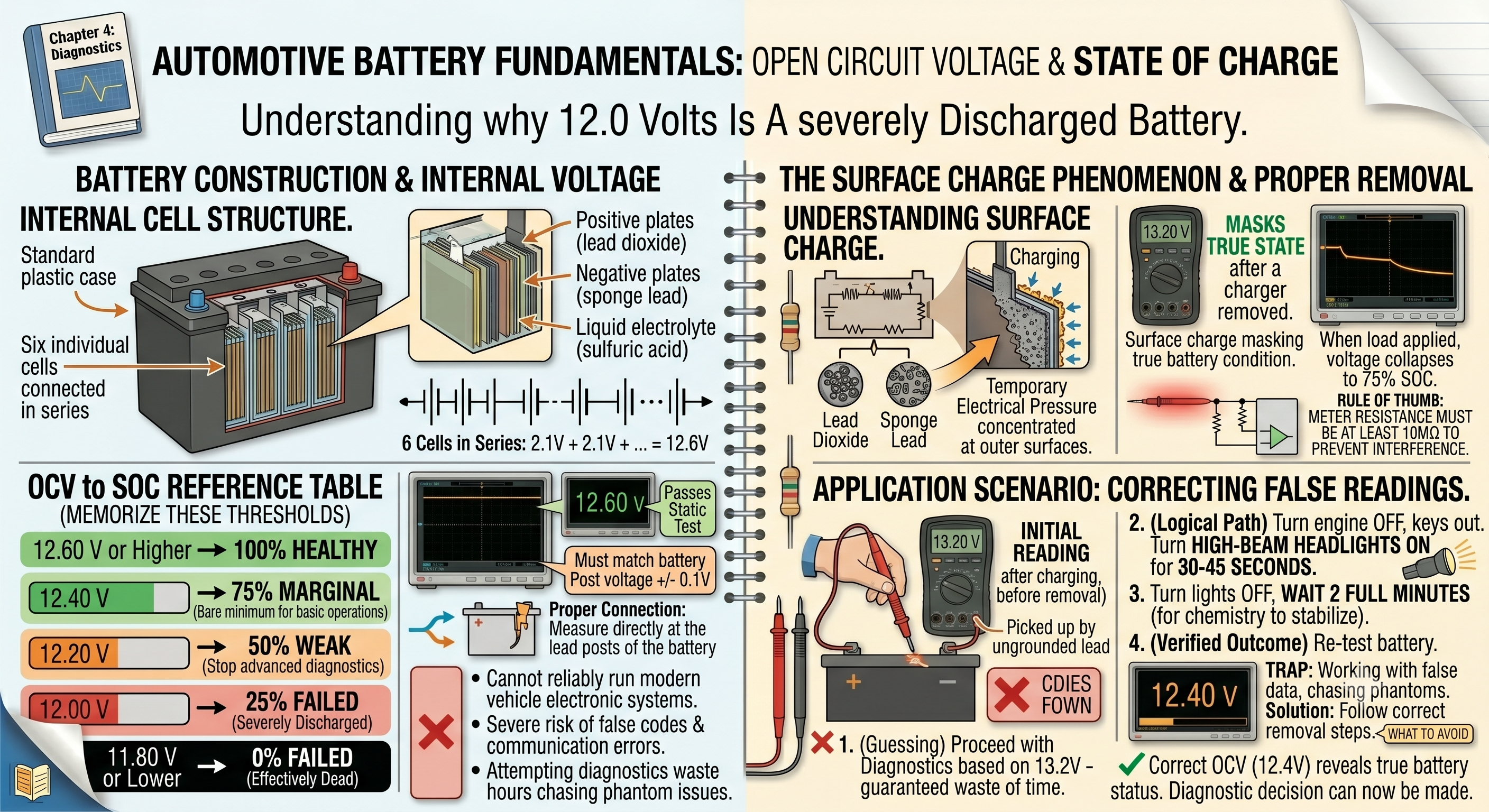
The standard automotive lead-acid battery is the heart of the vehicle's electrical system, yet it is one of the most misunderstood components on the road today. A healthy, fully charged twelve-volt battery does not rest at twelve volts. In fact, a battery resting at exactly 12.0 volts is severely discharged and incapable of reliably running a modern vehicle's electronic systems. To diagnose these systems accurately, you must memorize the direct relationship between open circuit voltage and the battery's state of charge.
A standard flooded lead-acid battery is made up of six individual cells connected in series inside a plastic case. Each individual cell, when fully charged, produces approximately 2.1 volts. When you connect six of these cells in series, their voltages add together. This gives us the industry-standard resting voltage for a 100% state of charge:
- 12.6 Volts or higher: 100% State of Charge
- 12.4 Volts: 75% State of Charge
- 12.2 Volts: 50% State of Charge
- 12.0 Volts: 25% State of Charge
- 11.8 Volts or lower: 0% State of Charge (effectively dead)
These numbers are absolute. There is no room for interpretation here. If you hook up your meter to a battery and read 12.4 volts, that battery is only at a 75% state of charge. In a modern vehicle packed with networks, sensors, and actuator modules, a 12.4-volt reading is the bare minimum acceptable limit for basic operations. In professional diagnostics, our rule in the shop is simple and uncompromising: if a vehicle's battery measures anything under 12.4 volts, we do not perform advanced diagnostics. We do not attempt to program modules, we do not run diagnostic sweeps on communication buses, and we do not chase sensor codes. The reason for this strict limit is that low voltage directly causes data corruption during high-speed communication; when modules lack sufficient electrical pressure, their logic thresholds shift, causing binary ones and zeros to distort, which corrupts the data packets traveling across the network and results in permanent programming failures or false diagnostic trouble codes. Attempting to diagnose a modern vehicle with a partially discharged battery is a guaranteed way to waste hours chasing phantom codes, communication dropouts, and false sensor readings.
The chemical reaction inside a lead-acid battery is reversible. When the battery is discharging, lead dioxide on the positive plates and sponge lead on the negative plates react with the sulfuric acid in the electrolyte to form lead sulfate on both plates, converting the liquid electrolyte into mostly water. When we apply a charging voltage from an alternator or a battery charger, we reverse this chemical process. The lead sulfate is broken down, the plates return to lead dioxide and sponge lead, and the acid concentration in the water increases. This chemical dance is highly efficient, but it leaves behind a temporary side effect that can easily trick an inexperienced technician: surface charge.
Surface charge is an artificially high voltage reading that remains on the surface of the battery plates immediately after charging. When a battery is being charged, the chemical activity concentrated at the outer surface of the plates produces a temporary electrical pressure that does not reflect the actual state of charge of the entire mass of the plates. If you test a battery immediately after taking a car off a battery charger, or right after shutting off the engine, your multimeter might display 13.0 volts, 13.2 volts, or even higher. This is not a super-charged battery. It is a surface charge masking the true state of the battery. If you base your diagnostics on this reading, you are working with false data.
To obtain an accurate Open Circuit Voltage reading, you must remove this surface charge before connecting your meter. There are two primary ways to do this. The first method is to let the battery sit undisturbed for at least two to four hours, allowing the chemical activity inside the plates to equalize naturally. However, in a busy repair shop, you rarely have the luxury of letting a customer's vehicle sit idle for several hours just to get a baseline voltage reading. You need a faster, more practical solution.
The second, more practical method is to apply a temporary electrical load to the battery to bleed off the surface charge. To do this, ensure the engine is off and the keys are out of the ignition. Turn on the vehicle's high-beam headlights for thirty to forty-five seconds. This moderate electrical load forces the battery to quickly exhaust the superficial chemical energy resting on the outer surfaces of the plates. After forty-five seconds, turn the headlights off and wait two full minutes. This waiting period allows the chemistry inside the battery to stabilize. Once those two minutes have passed, the voltage reading you get across the battery terminals will be a true, accurate representation of the battery's actual state of charge.
Measurement Methodology: Open Circuit Voltage Testing
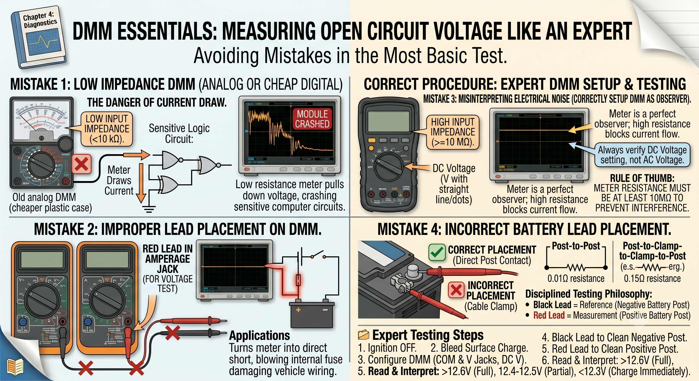
Measuring open circuit voltage seems simple, but small errors in your setup can lead to misleading measurements. To perform this test like an expert, you must understand your primary diagnostic tool: the Digital Multimeter, or DMM. A high-quality automotive DMM is designed to have very high internal resistance, usually ten megohms or more, when set to measure voltage. This high impedance is critical. It means that when you connect the meter leads to a circuit, almost no current flows through the meter itself. The meter acts as a perfect observer, measuring the electrical pressure without pulling down the circuit or interfering with the components you are testing.
If you were to use an old-style analog meter or a cheap, low-impedance digital meter on a modern vehicle, the meter itself would draw current from the circuit it is measuring. This current draw can pull down sensitive computer circuits, causing modules to crash, or worse, it can overload and destroy delicate transistors inside an engine control module. Always verify that your DMM is rated for at least ten megohms of input impedance before touching it to any vehicle system.
To prepare your DMM for an open circuit voltage test, start by inserting your test leads into the correct jacks on the meter face. The black lead always goes into the common jack, labeled COM. The red lead goes into the voltage jack, which is typically marked with a V and the Greek letter omega for ohms. Never plug your red lead into the amperage jacks when you intend to measure voltage. Doing so turns your meter into a direct short circuit, which will instantly blow the meter's internal fuse or damage the vehicle wiring the moment you touch the leads to power and ground.
Next, turn the selector dial on your meter to the DC Voltage setting. On most meters, this is represented by a capital letter V with a straight line and three dots above or next to it. The straight line represents Direct Current, which is the type of electricity used in automotive systems. Do not select the V with a wavy line above it, as this is for Alternating Current, which is used in household wiring and is not appropriate for basic automotive battery testing.
Once your meter is configured, you must adopt a disciplined testing philosophy. In our shop, we teach the black lead as reference, red lead as measurement philosophy. This means that you always connect your black meter lead to the ultimate ground reference point of the system you are testing. When testing a battery's open circuit voltage, this means placing the black lead directly on the negative battery post. Not the cable clamp, not the vehicle frame, and not the engine block. Place the lead directly on the lead post of the battery itself. This ensures that your reference point is the actual negative terminal of the chemical cell package.
With your black lead firmly secured to the negative post, take your red lead and place it directly on the positive lead post of the battery. Again, avoid placing the lead on the terminal clamp or the nut securing the cable. By touching the clean, bare lead of the battery posts directly, you bypass any potential resistance that might exist between the battery posts and the cable clamps. Look at the display on your meter. The reading you see is the true Open Circuit Voltage of the battery. Let us look at how this process works in practice:
- Ensure the vehicle's ignition switch is in the off position and all accessories are turned off.
- If the vehicle has been driven recently or connected to a charger, turn on the high-beam headlights for forty-five seconds to bleed off the surface charge, then turn them off and wait two minutes.
- Set your DMM to the DC Voltage setting and verify that your leads are plugged into the COM and V jacks.
- Connect the black meter lead directly to the clean negative battery post.
- Connect the red meter lead directly to the clean positive battery post.
- Read the voltage display on your DMM. If the reading is 12.6 volts or higher, the battery is fully charged. If the reading is between 12.4 and 12.5 volts, the battery is partially discharged but acceptable for basic testing. If the reading is 12.3 volts or lower, stop your diagnostics and charge the battery immediately.
This simple, disciplined approach ensures that you always begin your diagnostics with a clear, accurate understanding of your power source. It prevents you from making the critical mistake of chasing complex wiring or computer faults when the real problem is simply a discharged battery.
Dynamic vs. Static Testing: The Illusion of Potential
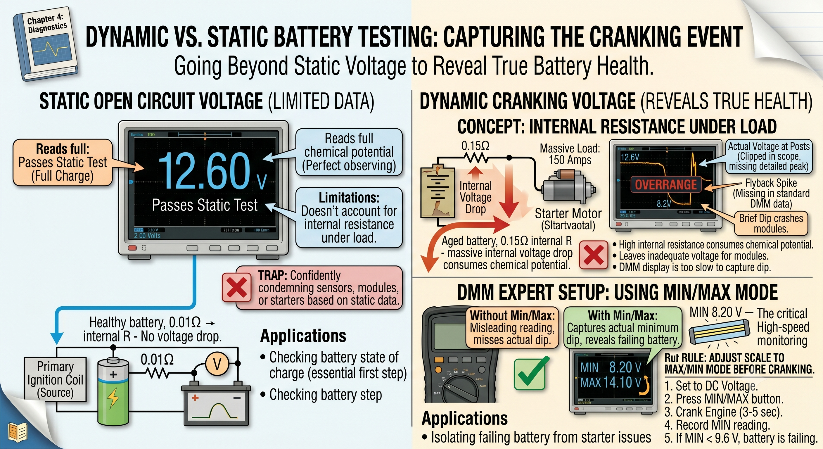
One of the most common traps that catches intermediate technicians is relying solely on static testing. A static test is a measurement taken when the circuit is inactive and no current is flowing. An open circuit voltage test is a perfect example of a static test. While this test is an essential first step, it has a major limitation: it cannot tell you how the battery will perform under a real-world load.
You will frequently encounter batteries that pass a static open circuit voltage test with flying colors, showing a perfect 12.6 volts on your meter, yet completely fail the moment the customer turns the key to start the engine. This happens because voltage is only one part of the electrical equation. To understand why a battery can show 12.6 volts statically but collapse under load, you must understand the concept of internal resistance.
Inside every battery, there is a natural resistance to the flow of current. In a healthy battery, this internal resistance is extremely low, often measured in milliohms. When you connect your high-impedance multimeter to the battery posts to take a static reading, the meter draws almost no current. Because there is no current flowing through the battery's internal resistance, there is no internal voltage drop. The meter reads the full chemical potential of the cells. The battery looks perfect.
However, when you turn the key to start the engine, you are no longer asking the battery to supply a tiny fraction of a milliamp to a voltmeter. You are asking it to supply 100 to 200 amps of current to the starter motor. This massive current flow must pass through the battery's internal chemical pathways. If the battery is aged, sulfated, or has damaged internal plate connections, its internal resistance will be significantly higher than normal.
According to Ohm's Law, when current flows through a resistance, a voltage drop is created across that resistance. The voltage drop inside the battery is equal to the current flowing multiplied by the internal resistance of the battery. If the battery has high internal resistance, a massive portion of its chemical potential will be consumed just trying to push that current through its own internal pathways. This leaves very little voltage available at the battery posts to power the vehicle's electrical system. Under the heavy load of the starter motor, the voltage at the posts can instantly drop from 12.6 volts down to 8.0 volts, 6.0 volts, or even lower.
This drop in voltage under load is why dynamic testing is so critical. A dynamic test is a measurement taken while the circuit is active and under load. To perform a dynamic cranking voltage test, you use your DMM to monitor what happens to the battery voltage during the actual cranking of the engine. This is where you will see the true health of the battery revealed.
When you crank the engine, the starter motor draws a massive surge of current to break the engine loose and get it spinning. During this initial surge, the battery voltage will quickly drop to a minimum point, and then rise slightly as the engine begins to spin and the starter motor's current draw stabilizes. This lowest voltage point recorded during cranking is the critical metric you must capture. In a healthy twelve-volt system, the battery voltage should never drop below 9.6 volts during a normal engine crank at room temperature.
If the voltage drops below 9.6 volts during cranking, the battery is either severely discharged or has high internal resistance and is failing. This drop in voltage has immediate consequences for the rest of the vehicle. Modern electronic control modules are designed to operate within a specific voltage window, usually between 9.0 and 16.0 volts. If the system voltage drops below 9.0 volts during cranking, these computer modules will begin to shut down, reboot, or enter a glitch state. They simply do not have the electrical pressure they need to keep their internal processors running.
When the cranking event ends and the starter motor disengages, the heavy load on the battery is removed. At this point, you will observe a phenomenon known as bounce back voltage. A healthy battery will quickly bounce back to its original resting voltage, or very close to it, within a few seconds of the load being removed. An unhealthy or deeply discharged battery, however, will struggle to recover. Its voltage will remain depressed, rising slowly and failing to reach its pre-crank levels. This slow recovery is a clear sign that the battery's chemical pathways are compromised and it can no longer deliver the energy the vehicle demands.
To capture this dynamic cranking event accurately with a standard digital multimeter, you must use a feature found on most professional-grade meters: the Min/Max recording function. When you set your meter to Min/Max mode, it constantly monitors the voltage signal at incredibly high speeds, capturing the absolute highest and lowest voltage values it sees. It stores these values in its internal memory, allowing you to read them after the test is complete.
Without the Min/Max function, your meter's standard display update rate, which is typically only three to four times per second, is too slow to capture the incredibly fast drop in voltage that occurs the instant the starter solenoid engages. You might see the numbers on the screen jump from 12.6 to 10.5, and then back up to 14.0 once the engine starts, completely missing the fact that for a fraction of a second, the voltage actually dipped down to 8.2 volts. That brief dip is more than enough to crash the Body Control Module or clear the memory in the Engine Control Unit, yet you would never know it happened without using the Min/Max function or an oscilloscope. Let us look at how to set up and execute this dynamic test:
- Ensure the battery has been verified as fully charged statically, with an open circuit voltage of at least 12.4 volts. If the battery is discharged, charge it before proceeding.
- Connect your DMM leads directly to the battery posts, keeping with our philosophy: black lead to negative post, red lead to positive post.
- Turn the meter dial to the DC Voltage setting.
- Press the MIN/MAX button on your meter. You should see a small indicator on the screen showing that the recording mode is active.
- Get into the driver's seat and crank the engine for three to five seconds. If the vehicle is equipped with a push-button start, allow the system to perform its normal starting cycle.
- Once the engine is running or the cranking cycle has finished, return to your meter and press the MIN/MAX button repeatedly to cycle through the recorded values. Locate the MIN reading.
- Analyze the minimum voltage recorded. If the minimum voltage remained above 9.6 volts, the battery and starter circuit are performing within acceptable limits. If the minimum voltage dropped below 9.6 volts, the battery is weak, the starter motor is drawing excessive current, or there is severe resistance in the primary battery cables.
By comparing your static open circuit voltage reading with this dynamic cranking measurement, you get a complete picture of the battery's health. You move beyond guessing and start working with hard, empirical data that clearly separates battery issues from starter or wiring problems.
Diagnostic Thresholds: The Language of System Health
In the world of professional automotive diagnostics, you must establish clear, unambiguous thresholds for what constitutes a good, marginal, or bad reading. You cannot afford to guess. In our shop, we have established a strict set of reference values that every technician must memorize and apply to every vehicle that comes through the door. These thresholds are not arbitrary; they are rooted in the physical requirements of modern automotive electronics.
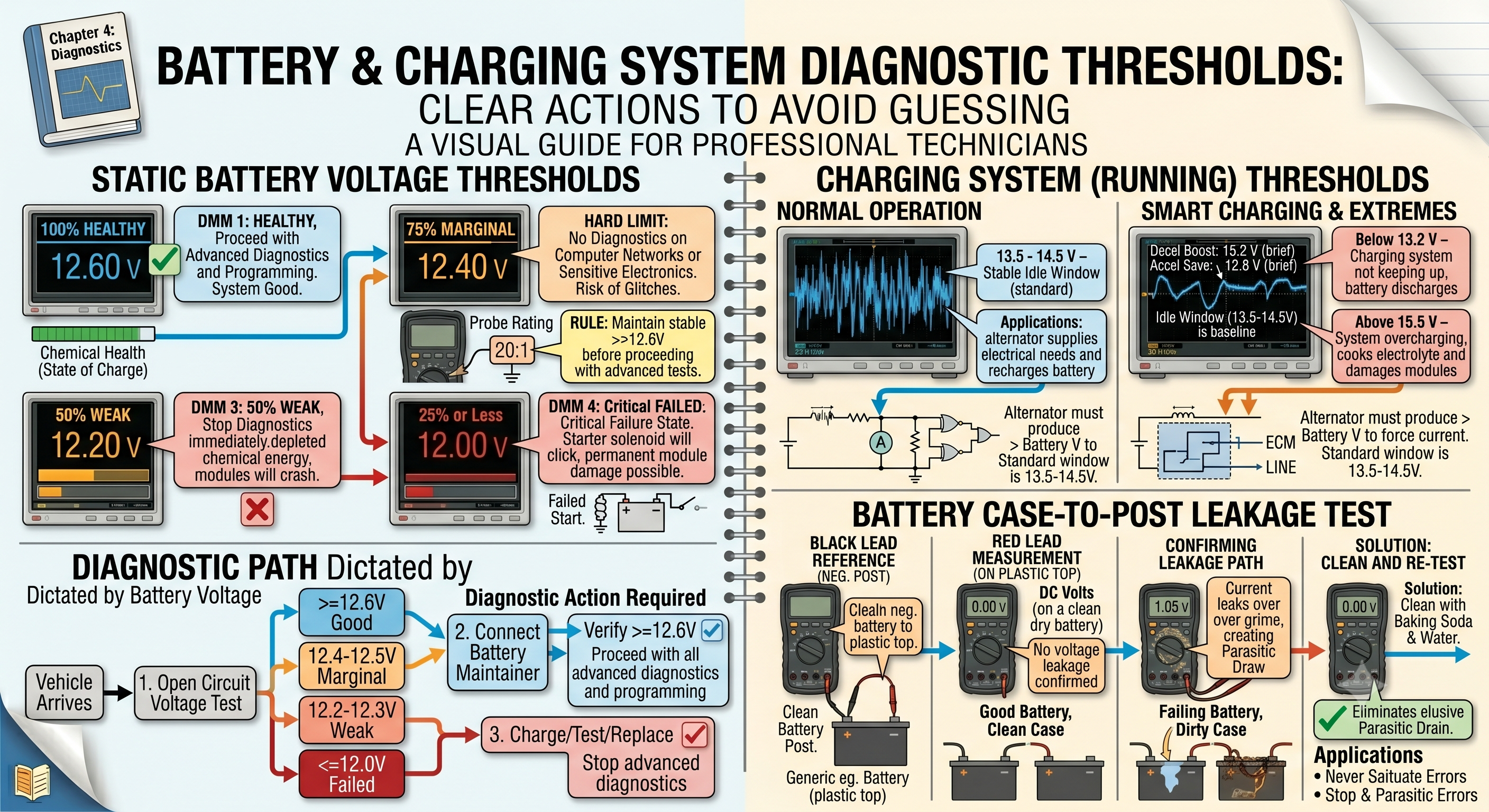
Let us look at these critical thresholds in detail. When you are performing an open circuit voltage test on a resting battery, your meter is telling you the state of charge of the battery chemistry. A reading of 12.6 volts or higher is your gold standard. This indicates a 100% state of charge. The battery is fully healthy, the chemical balance inside the cells is optimal, and there is plenty of electrical pressure available to run the vehicle's systems. This is the only state in which a battery should be allowed to enter advanced diagnostic procedures.
A reading of 12.4 volts represents a 75% state of charge. While this is often enough to start a healthy engine, it is marginal. In our shop, this is our hard limit. If a battery is at 12.4 volts, we do not perform diagnostic work on the vehicle's computer networks or sensitive electronics. The risk of low-voltage glitches distorting our diagnostic data is simply too high. We will connect a battery maintainer to the vehicle to bring the voltage up to a stable 12.6 volts or higher before proceeding with our tests.
A reading of 12.2 volts represents a 50% state of charge. For all practical diagnostic purposes on modern vehicles, a battery at 12.2 volts is considered dead. At this level of charge, the chemical energy in the battery is severely depleted. If you attempt to run diagnostic scans, program modules, or perform key-on, engine-off testing at 12.2 volts, you will almost certainly encounter communication errors, false trouble codes, and module dropouts. The battery must be placed on a battery charger immediately.
Any reading of 12.0 volts or lower represents a 25% or lower state of charge. This is a critical failure state. At 12.0 volts, the battery does not have enough energy to reliably power the vehicle's basic electronics, let alone crank the engine. If you attempt to start a car with a battery at 12.0 volts, the starter solenoid will likely just click, or the engine will crank incredibly slowly while the dashboard lights flash erratically. This low-voltage condition is not just a starting problem; it can cause permanent damage to electronic components if they are forced to operate in this state for extended periods.
To help visualize these thresholds and how they dictate your diagnostic path, refer to the table below:
| Voltage Reading | State of Charge | Diagnostic Action Required |
|---|---|---|
| 12.6V or Higher | 100% | System Good: Proceed with all diagnostic procedures and programming. |
| 12.4V to 12.5V | 75% | Marginal: Connect a battery maintainer before performing any diagnostics. |
| 12.2V to 12.3V | 50% | Weak: Stop diagnostics immediately. Charge the battery before proceeding. |
| 12.0V or Lower | 25% or Less | Failed: Battery is dead. Perform deep charge and battery health test; replace if necessary. |
In addition to testing the battery itself, you must also master the diagnostic thresholds for the vehicle's charging system. When the engine is running, the alternator is responsible for supplying all of the vehicle's electrical needs while simultaneously recharging the battery. To do this, the alternator must produce a voltage that is higher than the battery's natural resting voltage. If the alternator only produced 12.6 volts, no current would flow into the battery, because there would be no difference in pressure between the alternator and the battery. To force current back into the battery and recharge it, the alternator must raise the system voltage.
In a standard modern vehicle, the charging system should maintain a running voltage of between 13.5 and 14.5 volts under normal operating conditions. This provides enough electrical pressure to run all the vehicle's systems, from the ignition coils to the heated seats, while gently pushing current back into the battery to restore its charge. Some modern vehicles equipped with smart charging systems, where the Engine Control Module dynamically controls the alternator's output based on driving conditions and battery temperature, may briefly raise the voltage as high as 15.2 volts during deceleration, or lower it to 12.8 volts during acceleration to save fuel. However, under standard idle conditions with a normal electrical load, you should expect to see a stable reading in that 13.5 to 14.5-volt window.
If your running voltage reading drops below 13.2 volts, the charging system is not keeping up with the vehicle's electrical demands. The battery will slowly discharge as the vehicle is driven, eventually leading to a no-start condition. Conversely, if the running voltage rises above 15.5 volts for extended periods, the charging system is overcharging the battery. This high pressure will cook the liquid electrolyte inside the battery, causing it to boil and release highly flammable hydrogen gas. It can also damage sensitive control modules by subjecting their internal components to excessive electrical pressure.
Another critical test that is often overlooked is checking for battery case-to-post leakage. Over time, road dirt, moisture, and acid fumes can accumulate on the plastic top of the battery case. This layer of grime can actually become conductive, creating an unintended, low-resistance electrical path between the positive post and the negative post, or between the posts and the metal hold-down bracket. This leakage path acts as a tiny, constant drain on the battery, slowly discharging it over several days while the vehicle is parked.
To test for case leakage, you use your digital multimeter in a very specific way. Set your DMM to the DC Voltage setting. Connect your black meter lead directly to the clean negative battery post. Now, instead of touching the red lead to the positive post, touch the bare metal tip of the red lead to various spots on the plastic top of the battery case, especially around the areas surrounding the positive terminal and the hold-down bracket. Watch the meter display. On a clean, dry, healthy battery, the meter should read 0.0 volts, indicating no electrical pressure is escaping across the plastic surface.
If you see a reading on your meter, even if it is only 0.5 volts, 1.0 volt, or higher, you have confirmed that the battery case is leaking. This means that current is actively flowing across the dirty top of the battery, creating a constant parasitic draw. If you find case leakage, the solution is simple: thoroughly clean the top of the battery case with a mixture of baking soda and warm water to neutralize any acid residue, then dry it completely. Re-test with your meter to ensure the leakage path has been eliminated. This simple test can save you from replacing a battery that is actually healthy but simply dirty, while also resolving an elusive parasitic drain complaint.
Real-World Failure Analysis: The Domino Effect of Low Voltage
When a vehicle's electrical system voltage drops, the consequences are rarely confined to a single component. Instead, a low-voltage condition trigger a cascading domino effect throughout the vehicle's entire electronic infrastructure. One of the most common and complex behaviors you will encounter in modern vehicles is load shedding. This is a protective strategy programmed into the Body Control Module and other major controllers to preserve the vehicle's ability to run and drive when electrical energy is scarce.
When the BCM detects that the system voltage has dropped below a critical threshold, usually around 11.5 to 12.0 volts while the engine is running (indicating an alternator failure), it immediately begins to prioritize how the remaining electrical power is used. The computer categorizes every electrical feature on the vehicle based on its importance to safety and basic vehicle operation. Components that are not essential for keeping the vehicle moving or allowing the driver to see and steer are designated as non-essential.
The BCM will systematically shut down these non-essential systems to reduce the electrical load on the failing charging system. The first systems to be disabled are usually comfort and convenience features. You will see the heated seats turn off, the rear window defogger stop working, and the air conditioning compressor clutch disengage. If the voltage continues to drop, the BCM will take more aggressive action. It will shut off the infotainment system, disable the radio speakers, and turn off interior lighting. By shedding these heavy electrical loads, the vehicle attempts to stretch the remaining battery power as far as possible, prioritizing power for the ignition system, fuel injectors, electronic power steering, and safety systems like the Anti-lock Braking System and airbags.
To a driver, and to an inexperienced technician, this load shedding behavior can look like a series of unrelated, catastrophic component failures. A customer might bring a vehicle to your shop complaining that their radio suddenly died, their heater fan stopped working, and their instrument cluster is displaying multiple warning lights. If you begin by diagnosing the radio or the heater circuit, you will waste hours checking fuses, relays, and communication lines, only to find that everything is physically fine. The real culprit is simply that the alternator stopped charging, and the BCM did exactly what it was programmed to do: it shut down those non-essential systems to keep the engine running long enough for the driver to pull over safely.
Let us look at a real-world case study that perfectly illustrates this dynamic. A customer brought a late-model Chevrolet Malibu into our shop with a flatbed tow truck. The customer's complaint was that the vehicle had suddenly gone wild while driving down the highway. The radio screen went black, the power steering became incredibly heavy and difficult to turn, the ABS warning light illuminated, and then the vehicle completely died and refused to restart. When the technician first attempted to hook up a diagnostic scan tool to the vehicle's OBD-II port, the scan tool was unable to establish communication with any of the vehicle's control modules. It was as if the car's entire electronic network had vanished.
Instead of panicking and assuming that every computer on the vehicle had been fried by a power surge, the technician went back to the basics of our diagnostic framework. The first step was to perform an open circuit voltage test at the battery posts. The multimeter displayed a mere 11.8 volts. This is a completely dead battery, a 0% state of charge. At 11.8 volts, the vehicle's Body Control Module, which is responsible for routing power and wake-up signals to the rest of the modules on the network, had entered a glitch state. Its internal processors were caught in a continuous loop of trying to boot up, crashing due to the lack of electrical pressure, and trying to boot up again. Because the BCM was offline, the high-speed CAN-bus network was inactive, which is why the scan tool could not communicate with any module.
The technician did not attempt to clear codes or perform any network diagnostics in this state. Instead, they connected a high-quality jump pack to the battery posts, instantly raising the system voltage to a stable 12.6 volts. The moment the jump pack was connected, the BCM booted up cleanly, the instrument cluster came back to life, and the scan tool was immediately able to communicate with every module on the network. A quick scan of the system revealed over thirty different communication and low-voltage codes stored in various modules, all of them triggered by the low-voltage event.
With the system voltage stabilized, the technician was able to start the engine and perform a dynamic charging system test. The meter showed that with the engine running, the voltage at the battery posts remained at 12.0 volts, indicating that the alternator was completely dead and was not producing any output. The root cause of the entire failure sequence was simply a failed alternator. As the vehicle was driven, the alternator stopped charging, and the vehicle was forced to run entirely on the battery's reserve capacity. As the battery voltage steadily fell, the BCM began its load-shedding protocol, disabling the radio and other non-essential systems. Eventually, the voltage dropped below the threshold required to run the electronic power steering module, causing the steering to go heavy. Finally, the voltage fell so low that the fuel injectors and ignition coils could no longer operate, and the engine died.
This case study highlights the absolute necessity of establishing proper voltage baselines before attempting any advanced diagnostics. If the technician had not checked the battery voltage first and instead began replacing modules or tracing network wiring, they would have spent hours of diagnostic time on a vehicle that simply needed an alternator and a battery charge. Always verify your power and grounds before you look at anything else.
Troubleshooting Flowchart: The Logical Path to Resolution
To ensure that you never get lost in a complex electrical diagnosis, you must follow a logical, structured troubleshooting process. This process should be applied to every electrical issue you encounter, regardless of how simple or complex it may seem. By following a consistent path, you eliminate guesswork, avoid the temptation to throw unnecessary parts at the vehicle, and guarantee an accurate diagnosis every single time.
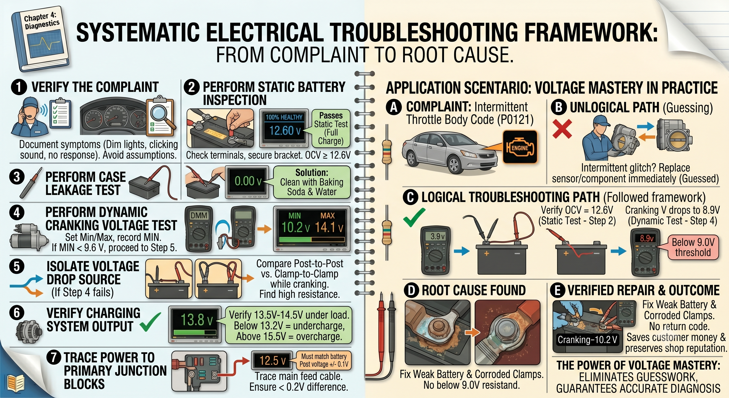
Below is a step-by-step diagnostic framework designed to take you from a customer complaint to a definitive, verified root cause. It begins at the absolute source of electrical pressure, the battery posts, and moves systematically outward to the primary power distribution network.
-
Verify the Complaint:
Before you touch a single tool, you must verify the customer's complaint. If the vehicle is a no-start, attempt to crank the engine and observe the symptoms. Do the dashboard lights dim or go out? Do you hear a rapid clicking sound from the starter solenoid? Is there no response at all when you turn the key? Document these observations carefully, as they provide critical clues about where to start your physical testing.
-
Perform a Static Battery Inspection:
Pop the hood and locate the battery. Perform a thorough visual inspection. Are the battery terminals clean and tight, or are they covered in green, corrosive acid buildup? Is the battery hold-down bracket secure, or is the battery free to vibrate and damage its internal plates? Use a digital multimeter to measure the Open Circuit Voltage directly at the lead posts of the battery. If the battery has been charged recently, remember to remove the surface charge by turning on the high-beam headlights for forty-five seconds before taking your measurement.
- If the OCV is 12.6V or higher, the battery is fully charged. Proceed to Step 4.
- If the OCV is 12.4V to 12.5V, the battery is partially discharged. Connect a battery maintainer to support the system while you continue your diagnostics.
- If the OCV is 12.3V or lower, the battery is depleted. Stop diagnostics, connect a battery charger, and bring the battery to a full charge before proceeding. If the battery will not accept a charge, replace it.
-
Perform a Case Leakage Test:
With your meter still connected to the negative battery post, touch the red lead to various points on the plastic top of the battery case. If you detect any voltage reading on the case surface, clean the battery thoroughly with a baking soda and water solution, dry it completely, and re-test. This ensures that a dirty case is not causing a parasitic drain that will discharge your newly charged battery.
-
Perform a Dynamic Cranking Voltage Test:
With the battery verified as fully charged, set your DMM to the DC Voltage setting and activate the Min/Max recording function. Connect your leads directly to the battery posts (black to negative, red to positive). Crank the engine and record the minimum voltage point.
- If the minimum cranking voltage remains above 9.6V, the battery has excellent capacity and low internal resistance. The primary power source is healthy. Proceed to Step 6 to verify the charging system.
- If the minimum cranking voltage drops below 9.6V, you have a weak battery, excessive current draw from the starter motor, or high resistance in the primary cables. Proceed to Step 5 to isolate the fault.
-
Isolate the Source of Cranking Voltage Drop:
If your cranking voltage dropped below 9.6 volts at the battery posts, you must determine if the drop is caused by a bad battery or by high resistance in the connections between the battery and the starter. To do this, move your meter leads from the lead posts of the battery to the cable clamps themselves. Repeat the cranking test.
- If the cranking voltage at the cable clamps is significantly higher than the voltage recorded at the battery posts, you have high resistance between the battery posts and the clamps. Clean the posts and clamps thoroughly, torque them to specification, and re-test.
- If the voltage still drops below 9.6 volts at the cable clamps, perform a voltage drop test on the primary positive and negative cables while cranking. If the cables are good, the battery is weak and must be replaced, or the starter motor is drawing excessive current and must be serviced.
-
Verify Charging System Output:
With the engine running, monitor the voltage at the battery posts. The voltage should quickly rise above the resting battery voltage as the alternator begins to charge.
- If the running voltage is between 13.5V and 14.5V under a moderate electrical load (headlights and blower motor on high), the charging system is operating correctly.
- If the running voltage remains below 13.2V, the alternator is undercharging or not charging at all. Check the alternator belt tension, the primary alternator connections, and the control signals from the ECM.
- If the running voltage rises above 15.5V, the alternator is overcharging. This is usually caused by a failed internal voltage regulator or a lost reference voltage signal from the ECM. Replace the alternator or service the control circuit immediately to prevent damage to the battery and vehicle modules.
-
Trace Power to Primary Junction Blocks:
Once you have verified that the battery and charging system are healthy, you must ensure that this electrical pressure is actually reaching the rest of the vehicle. Move your red meter lead from the battery positive post to the main feed terminal of the primary underhood fuse box (often called the Underhood Junction Block or Power Distribution Center). Keep your black lead connected to the negative battery post.
- If the voltage at the main feed terminal of the fuse box matches the voltage at the battery positive post within 0.1 volts, the primary feed cable is healthy. You can now proceed to test individual fuses and circuit branches.
- If the voltage at the fuse box is significantly lower than the voltage at the battery post (a difference of more than 0.2 volts), you have high resistance in the primary feed cable or the main fusible link. Perform a voltage drop test across this cable to locate and repair the restriction.
This systematic, step-by-step framework ensures that you never overlook the basics. It forces you to build your diagnostics on a solid foundation of verified power and ground, ensuring that when you do move on to testing complex computer networks and sensors, you can trust that any anomalies you find are actual circuit faults, not just the symptoms of a weak battery or a loose terminal clamp. This is the difference between a technician who guesses and a professional who knows.
To further illustrate the practical application of this troubleshooting sequence, let us consider a final real-world scenario. A technician is faced with an intermittent electronic throttle body fault code on a late-model SUV. The code suggests a sensor signal correlation issue. A less-experienced technician might immediately order a new throttle body assembly, assuming the sensor inside is bad. However, a technician following our diagnostic framework begins by checking the power source.
During a dynamic cranking voltage test, the technician notes that the battery voltage dips to 8.9 volts for a fraction of a second when the starter first engages. This brief dip is below the 9.0-volt threshold required to keep the Engine Control Module's internal memory and sensor reference circuits stable. While the engine starts and runs fine, that tiny split-second drop in pressure causes the ECM to lose its position memory for the throttle body blade. When the engine starts and the ECM reboots, it detects that the throttle blade is not where it expects it to be, and it sets a correlation code.
By replacing a weak battery and cleaning the corroded terminal clamps, the technician stabilizes the cranking voltage at 10.2 volts. The throttle body code never returns. The customer is saved from paying for an expensive throttle body they did not need, and the shop's reputation for accuracy and integrity is preserved. This is the power of voltage mastery. It is not just about understanding the physics of electrical pressure; it is about applying that understanding systematically to every vehicle that enters your bay. By mastering these concepts, you elevate your diagnostics from a guessing game to a precise, logical science.
Resistance and Voltage Drop: The Science of Restriction
In applied automotive electrodynamics, charge transport through a conductor is governed by the physical properties of the material, where resistance represents the opposition to electron flow. In any engineered automotive circuit, resistance is the designated driver of electrical behavior. The engineers who designed the vehicle calculated the exact…